Continuing work not finished in alog 61069 where we found the CO2X beam was misaligned. Table drawing T1200007.
- We re-checked that the beam centering: low on the second iris and FLIR (photo), high on BS1 and first iris. (I was previously incorrect that it was high on the FLIR, the flipped imagine of the masks confused me).
- TJ checked that all optics were not wobblery and tightened them to the table.
- Adjusted M5 and the output mirror to correct CO2 to irises alignment.
- We moved BS1 and the output mirror -14" (360mm) in -x.
- We noticed we were now not centered on the power meter so realigned with M6, BS1 and output mirror.
- We moved the imaging lens -14" and tweaked alignment.
- We realigned the imaging path of the beam to what we thought was the center of the FLIR. Adjusted IMG BS1 IMG M1,2,3. We actually think we were saturating the FLIR and are a little off in yaw so will re-check tomorrow.
- We realigned masks and their sensors and checked they were working in medm.
Still to do:
- Recheck FLIR and mask centering.
- Add visible alignment laser.
- Look into possible clipping of the table baffle adapter.
- Check medm power is calibrated.
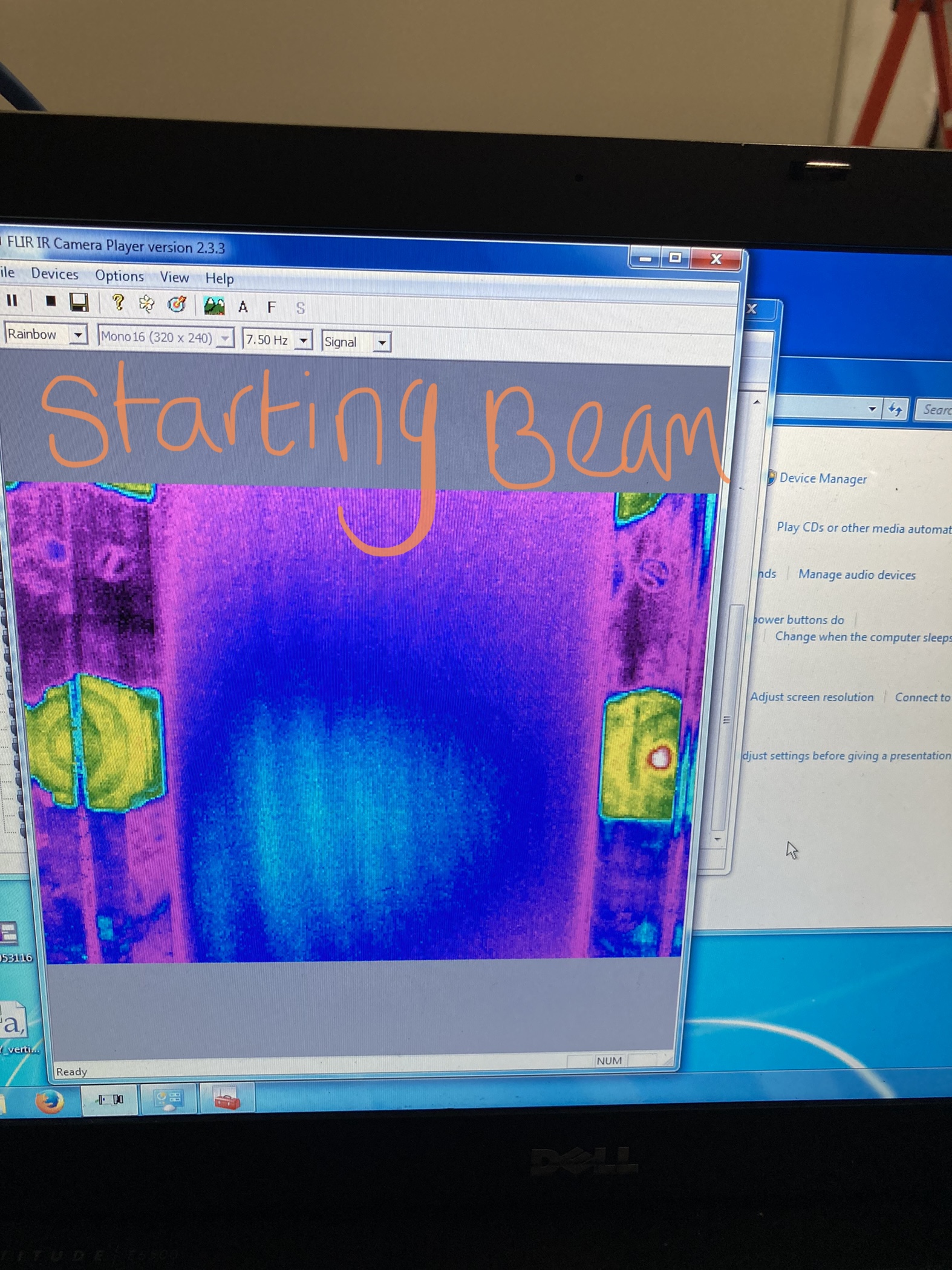
TJ, Camilla. We are still not happy with the CO2X beam as when using the central mask are getting a strange mode shape that we didn't seem to have before moving the masks and optics 360mm upstream. Photo of the before image is here.
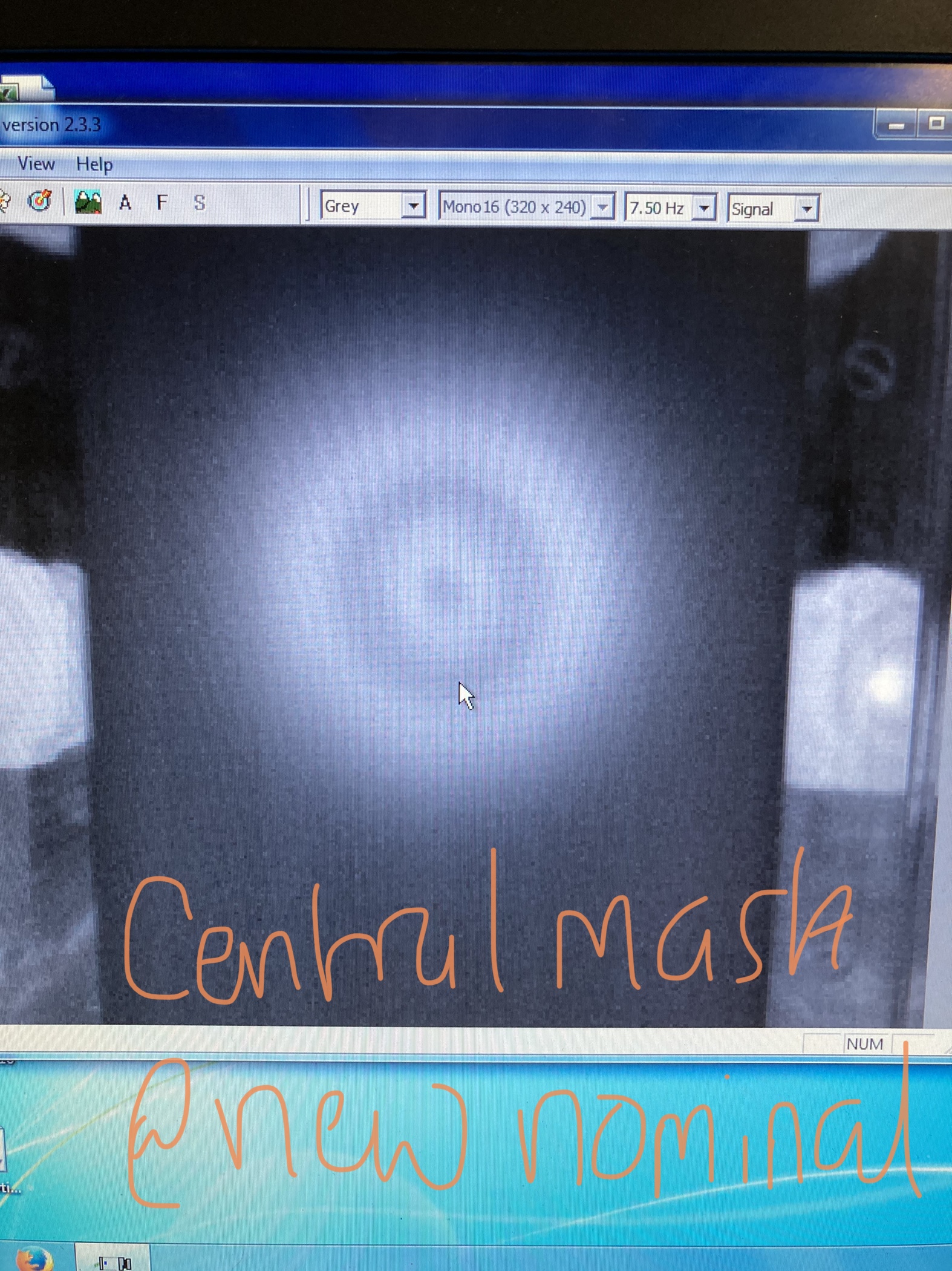
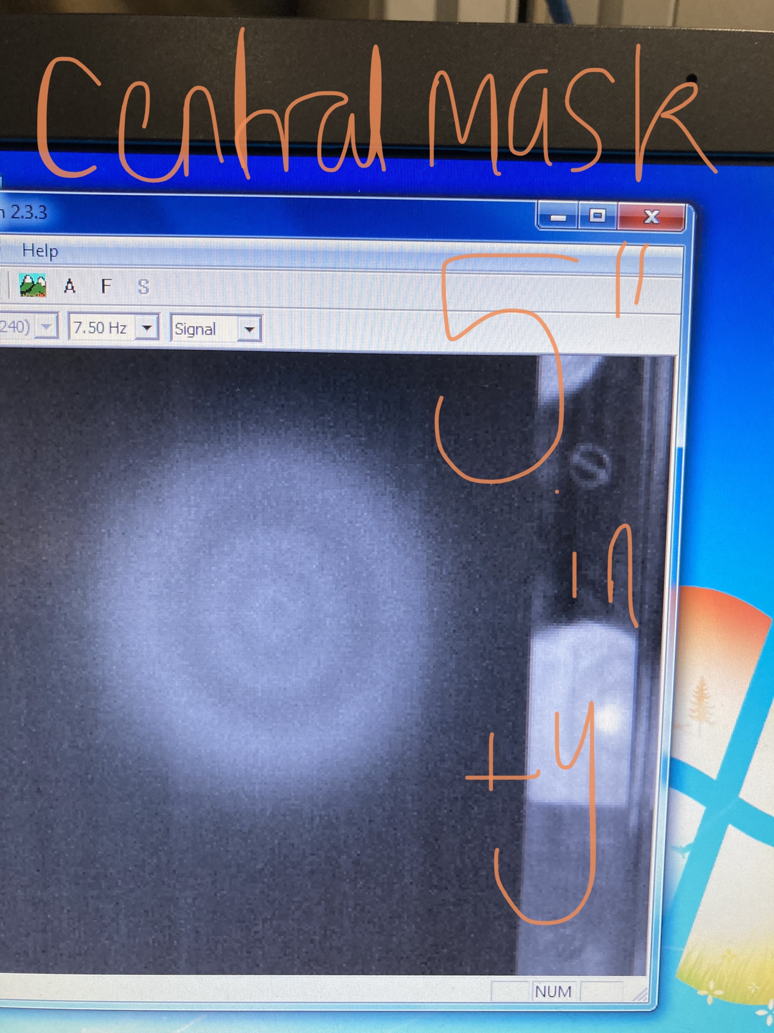
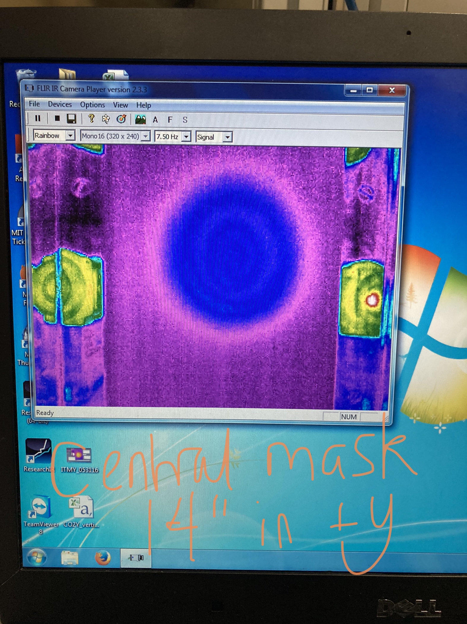
Today we very carefully made sure the beam CO2 beam was centrally aligned to masks and well aligned the imaging path. To try and get rid of the strange mode we moved the central mask:
- Horizontally across the beam until clipping was seen - no improvement
- Both downstream and upstream different amounts - the beam still had strange modes but the modes changed! We didn't find a 0,0 mode but could have checked more spots. Photos attached.
- Downstream 14" to account for mask move -360mm - no improvement.
Maybe this is because the beam is the wrong size when it hits the mask so we need to adjust the f=1m lens to adjust for this but then we would have expected a nice beam when the mask was 14" downstream (+y). I am unsure where the beam is collimated to know how far to move the lens L2 but information might be in T1500034.
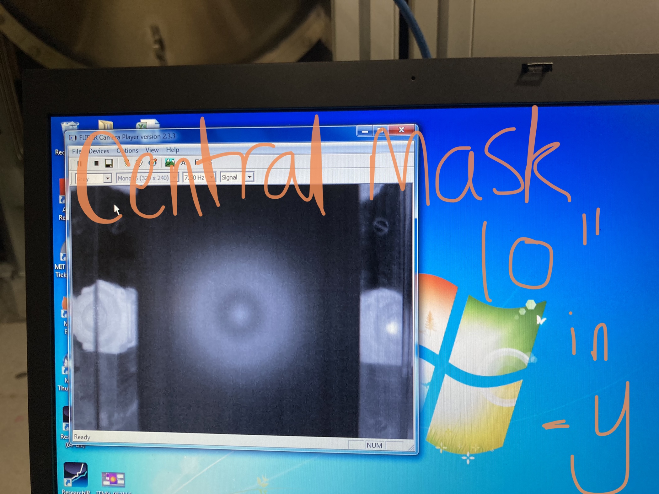
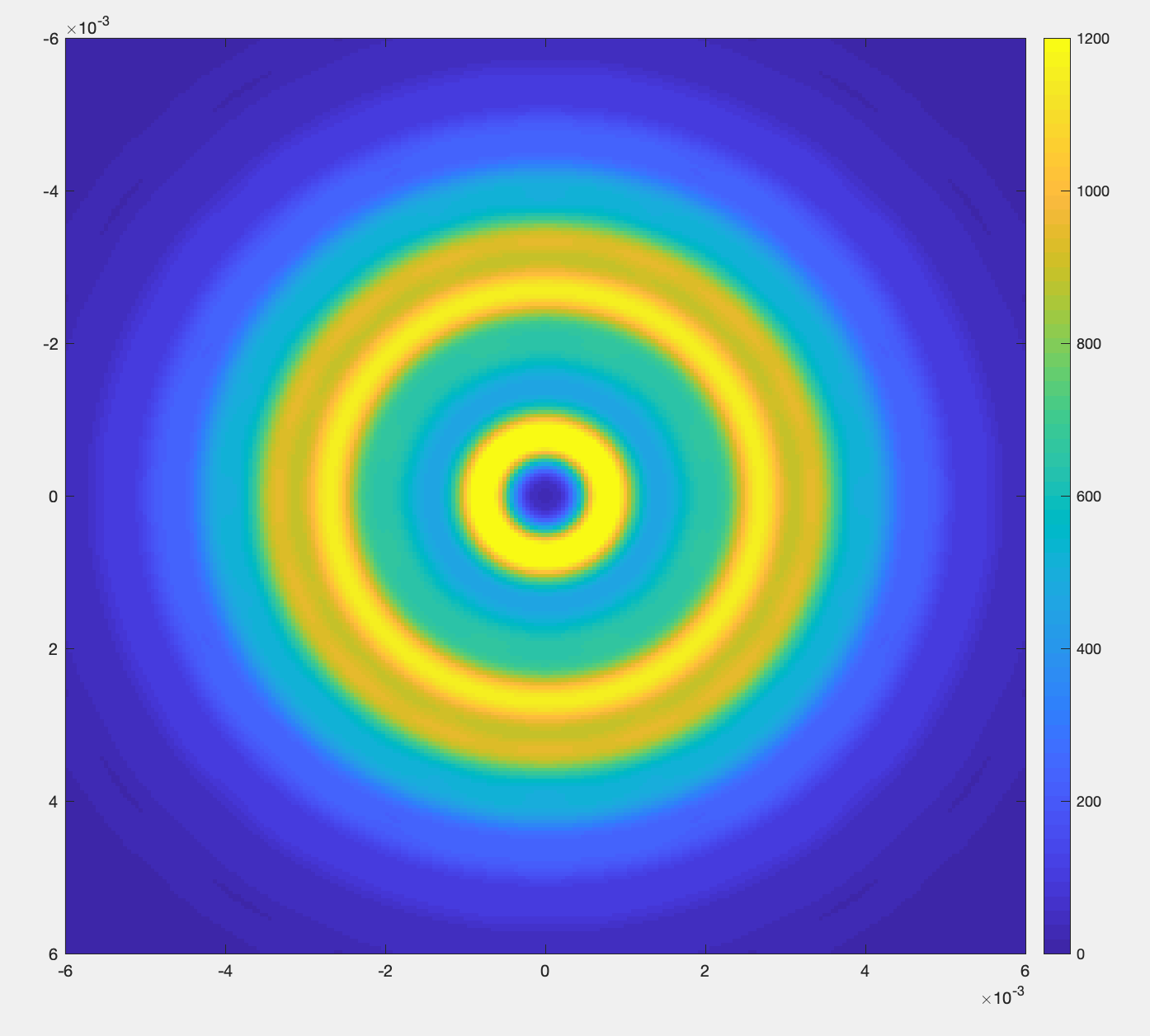
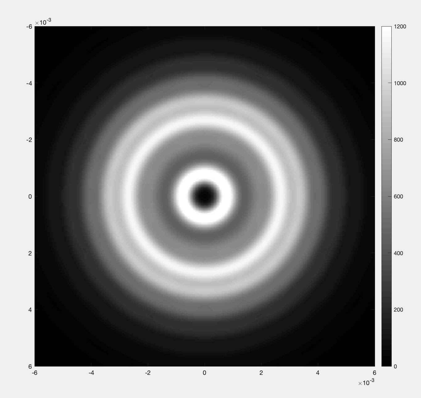
This might be diffraction. Here's a model of a large diameter CO2 beam going through a 10mm diameter aperture and then projected a further 60cm. It reproduces an annular pattern. It might be that the imaging lens is set up to image a plane other than the mask. I'd need exact distances between the mask, lens and imaging plane to model the effect precisely.
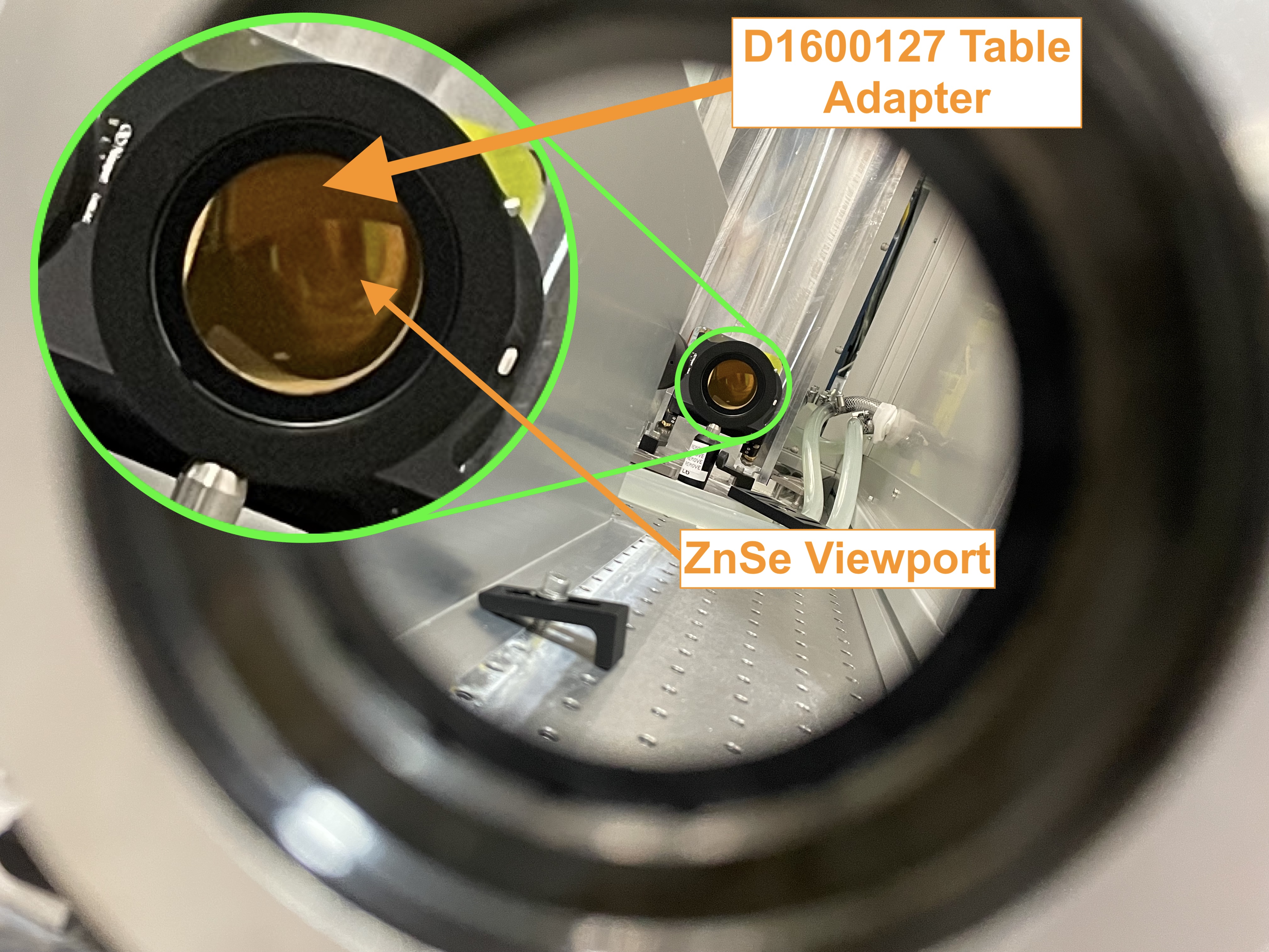
Yesterday we were able to get a good look at the interference of the TCS CO2 VP Enclosure to Table Adapter Interface Assy. (D1600127) just before the ZnSe viewport. After we moved the table we thought that it would be in the way, but this picture through the two irises clearly shows it. The assembly is at the limits of its adjustment, and we need to move another ~1in in the -X direction. We'll talk with Tyler and see if we can easily modify this assembly to move it, otherwise we may have to make a new part or get creative.
I have added new distances to a new tab in the googledoc started in alog 59715 (once finalized will add this to DCC). Table layout drawing= T1200007
| Laser to L1 (f=6") | 49" |
| Laser to L2 (f=1m) | 98" |
| Laser to central mask | 124" |
| Laser to FLIR | 248" |
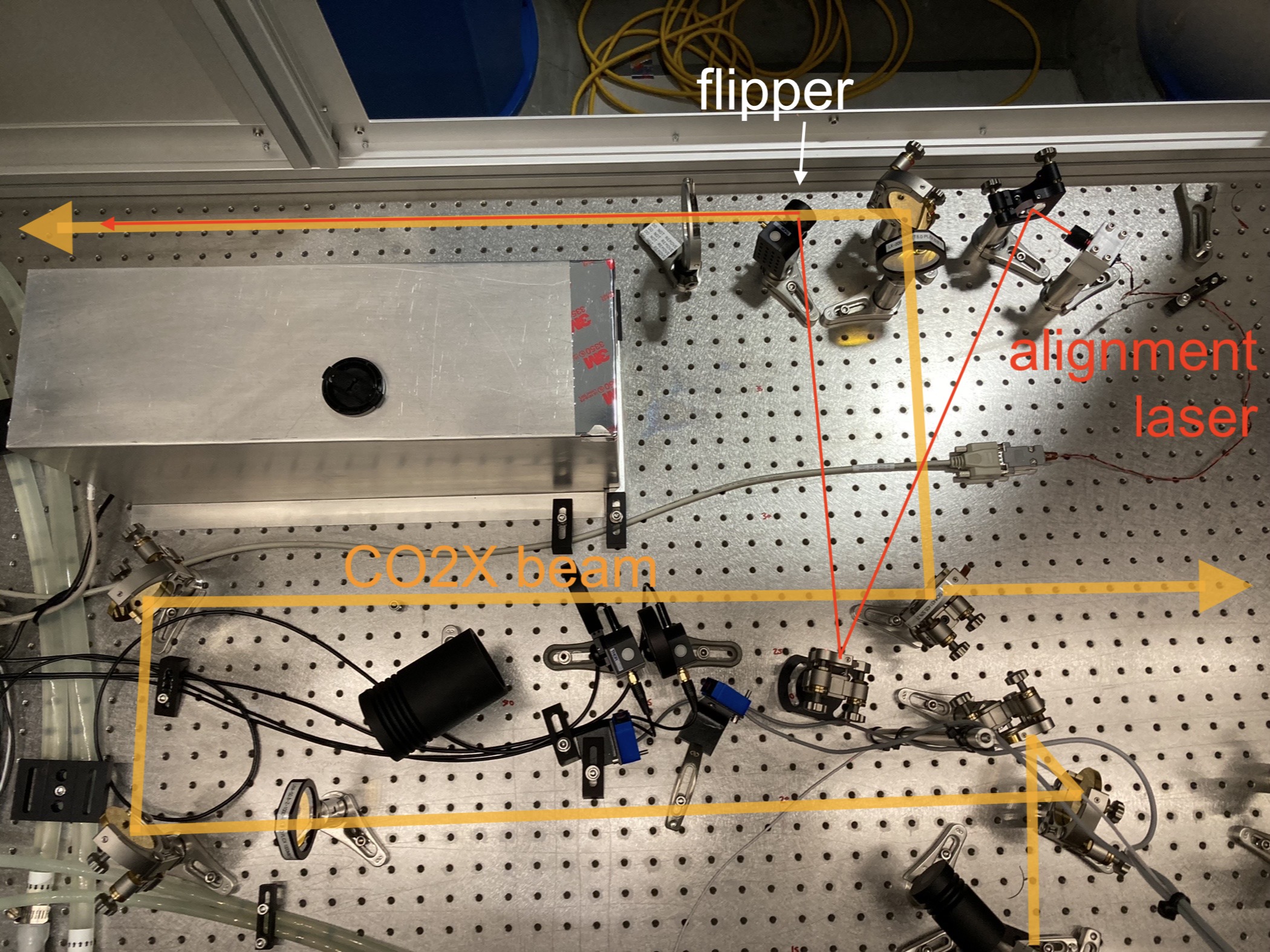
Photo of current layout attached. Flipper mirror between M5 and M6 is temporary.
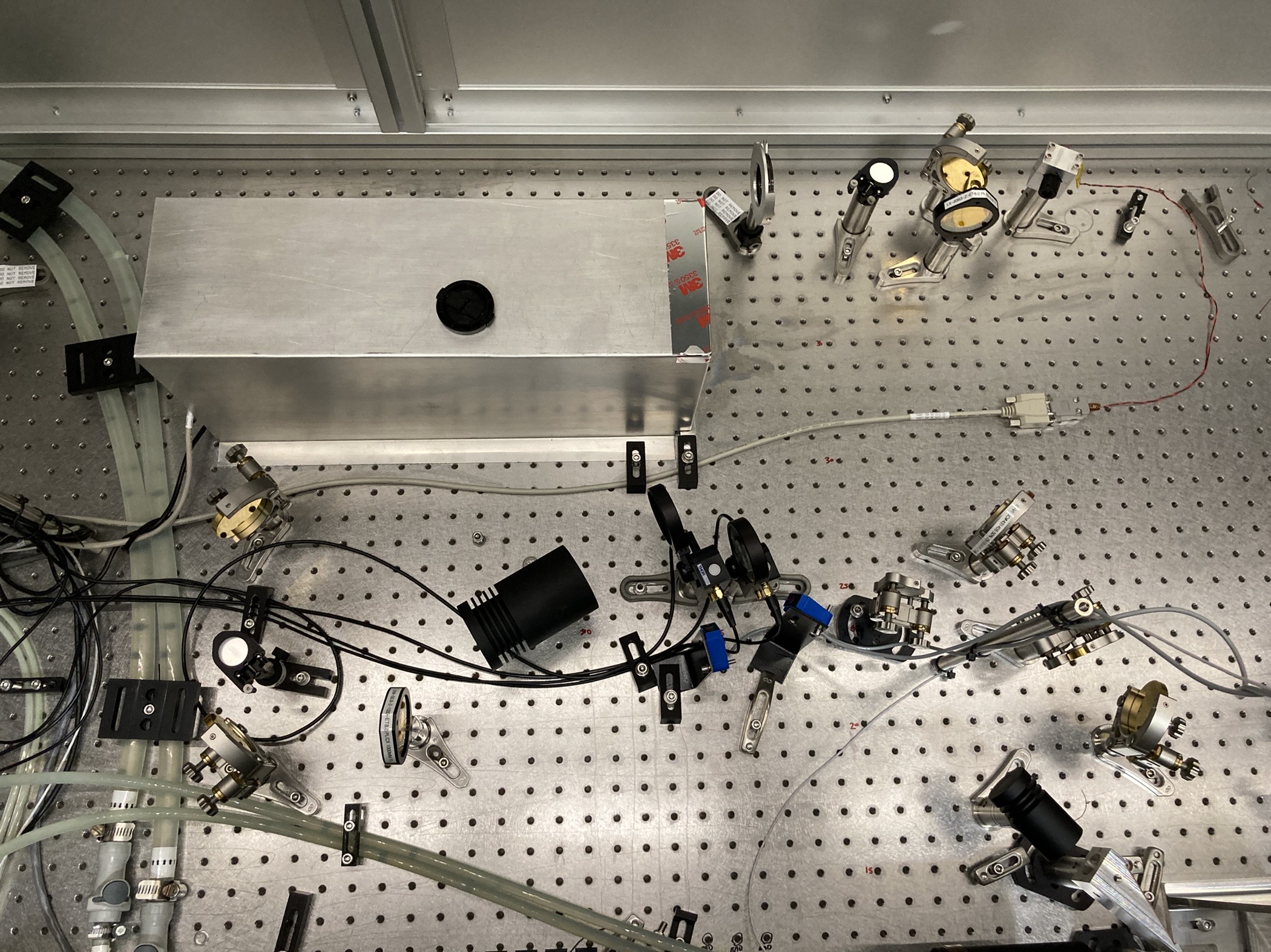
The adjustable flipper optic mount 9891 that was being used for the alignment laser had it's screw almost clipping the CO2 beam. I swapped it out for a non-adjustable MFF101 mount that sits much lower when flipped. This model can be motorized but there's no need for us to power it. Photo attached of new alignment laser set up. It has been aligned to the irises.
Interference of the TCS CO2 VP Enclosure to Table Adapter Interface Assy. just before the ZnSe viewport fixed. See alog 61577.