TJ Shaffer, Camilla Compton. Continuation of alog 61350. WP 10154.
Carlos upgraded our FLIR laptop to a windows10 machine to work with the ResearchIR 4 software, details in T2200033.
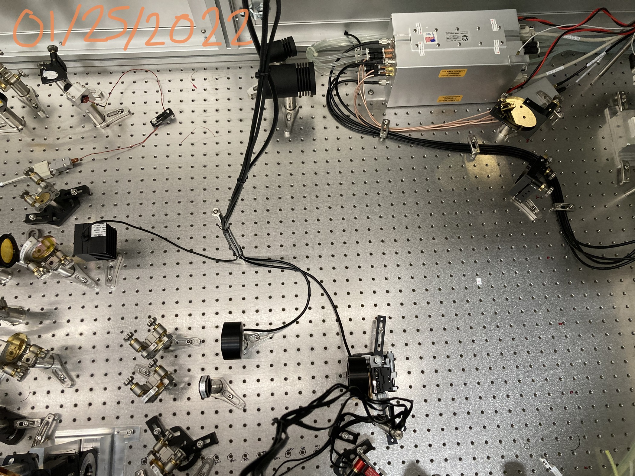
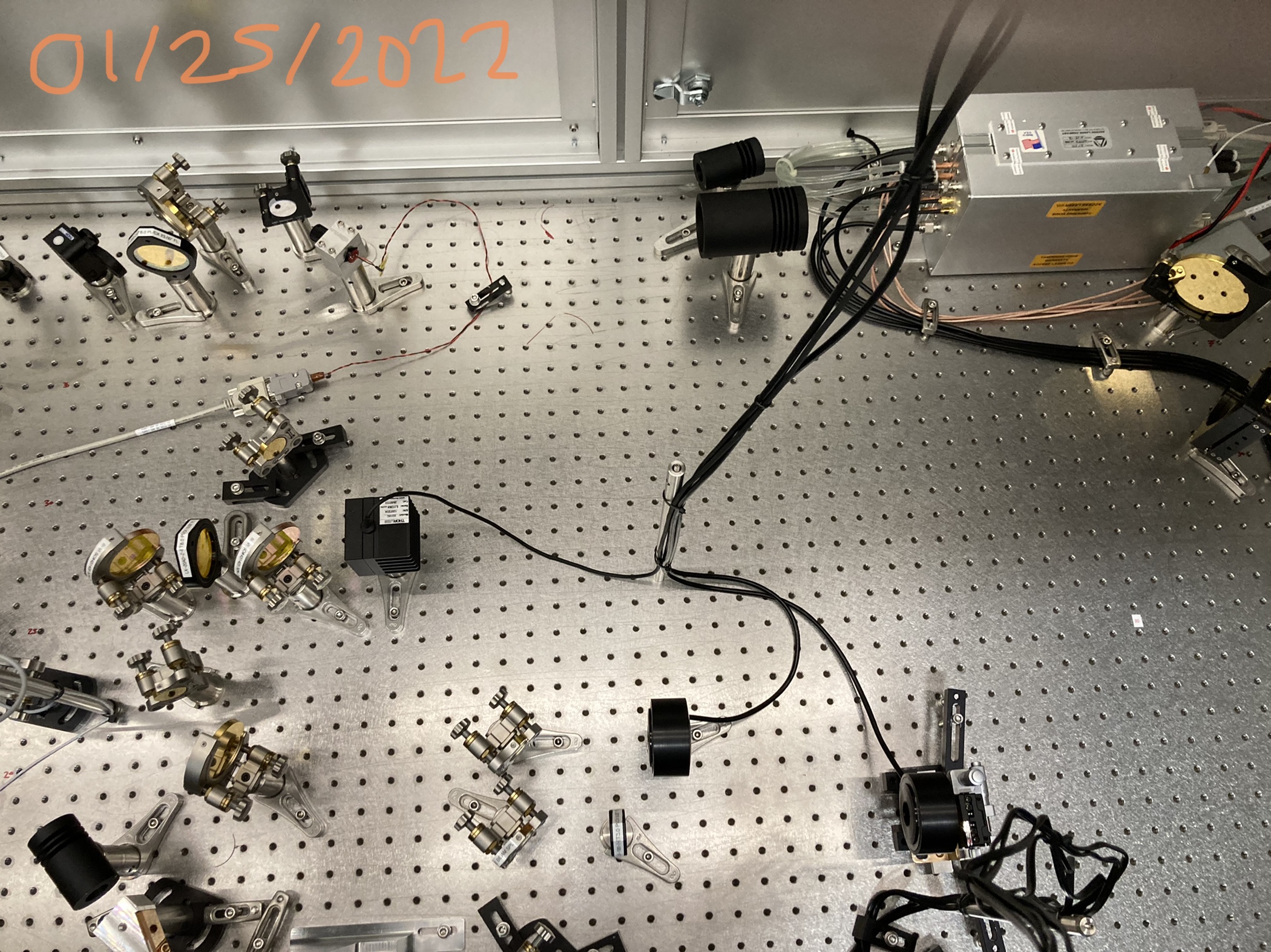
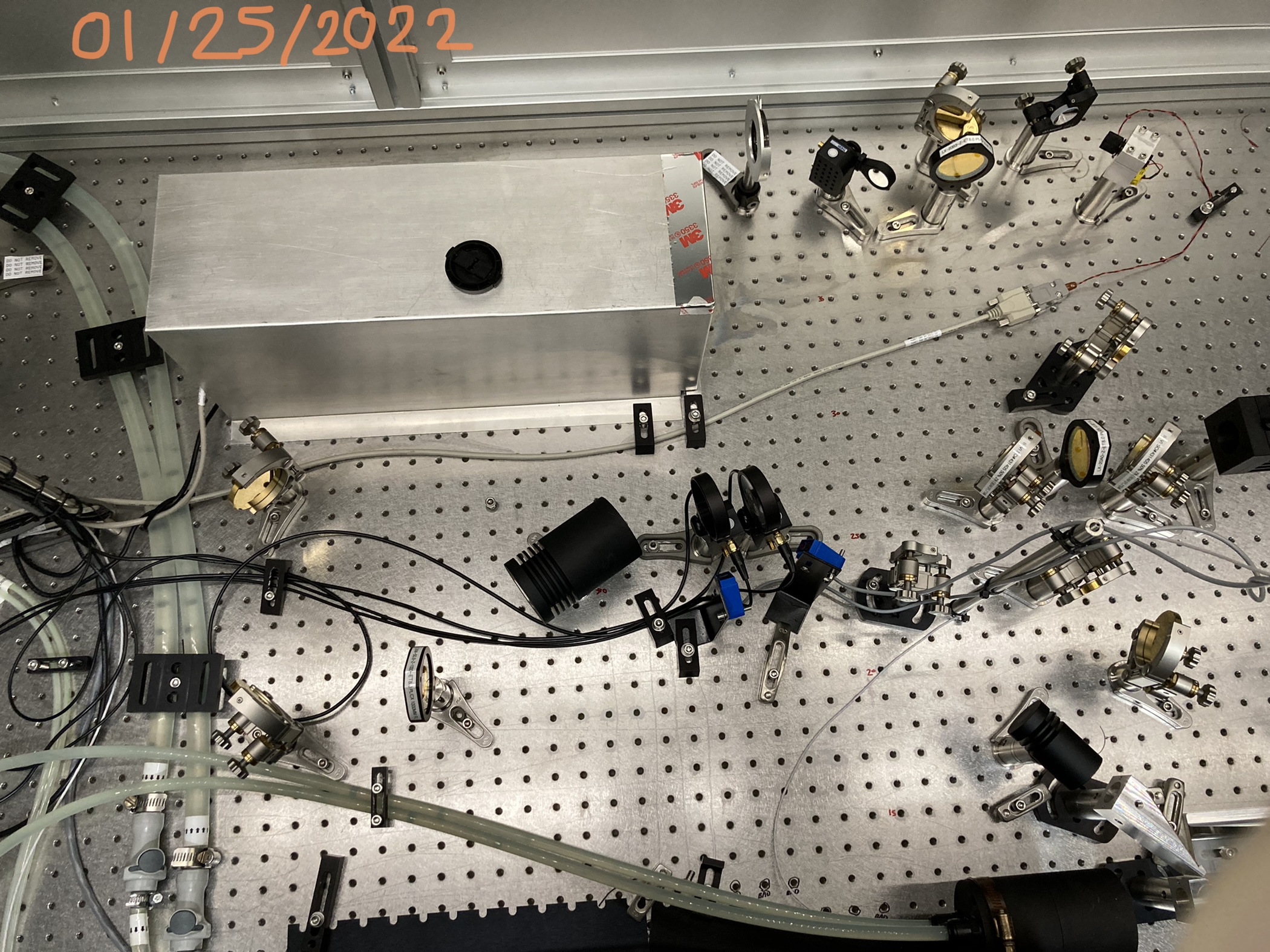
After Aidan's help we found that the issue strange mode shape issue reported in alog 61350 was just due to us not adjusting the imaging path which meant we did not have the FLIR camera at the correct location to see what the beam would be like on Compensation Plate X. We moved IMG L1, IMG BS, POW MET, IMG M1 14" in -x and IMG M2 and IMG M3 7" in -x to keep the distances between the masks and IMG L1 and the distance between IMG L1 and the FLIR the same as during O3. Optics names: T1200007.
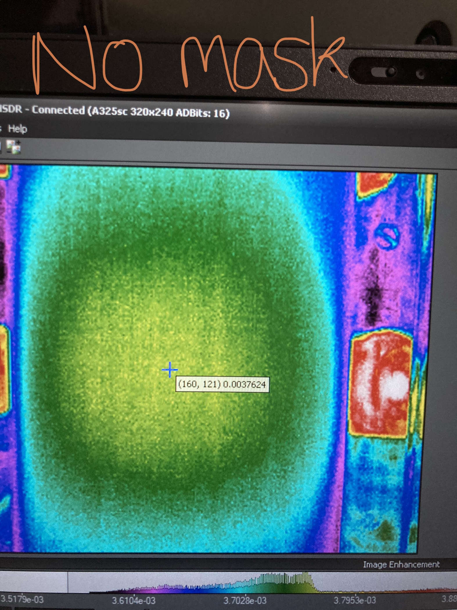
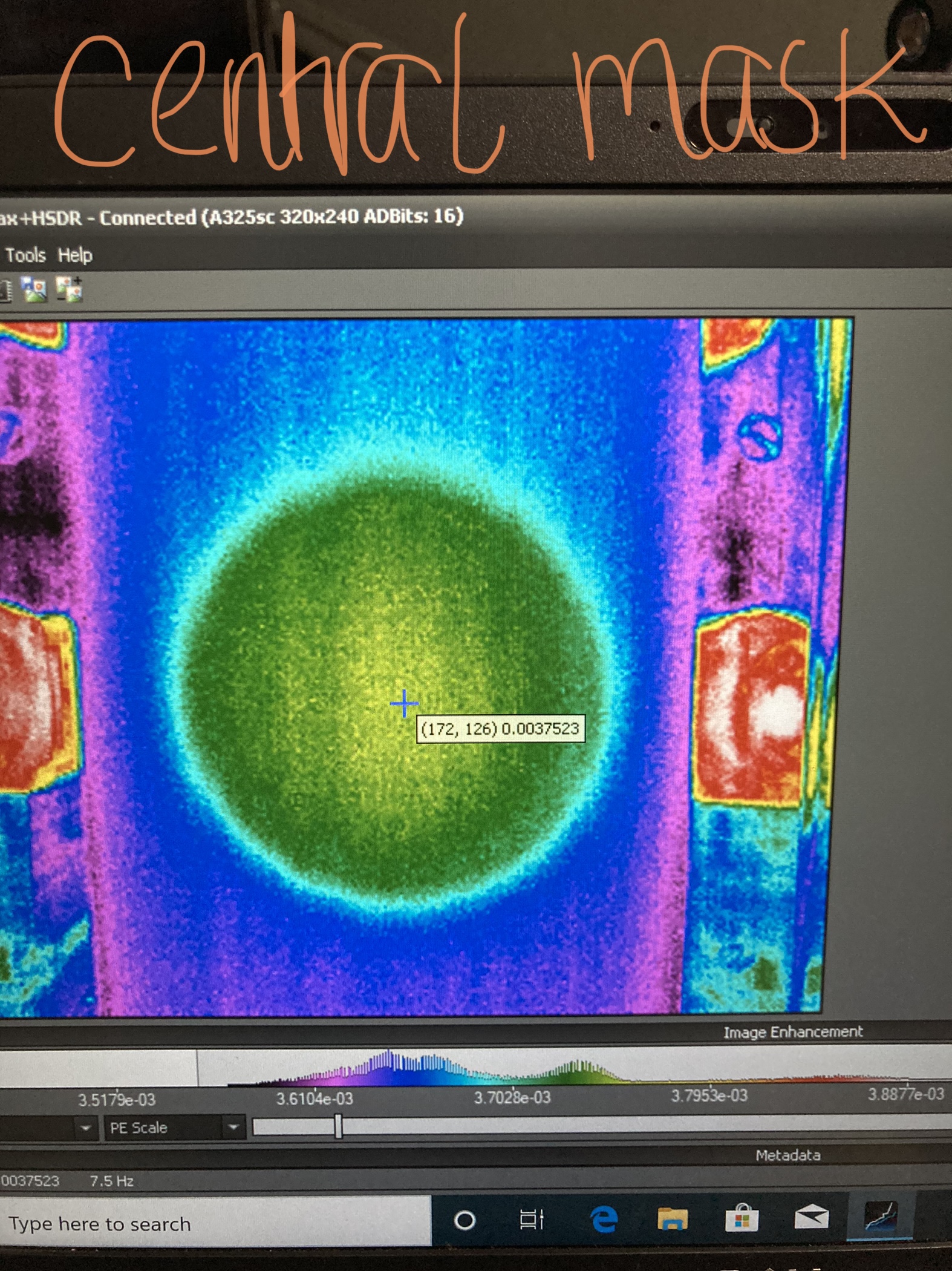
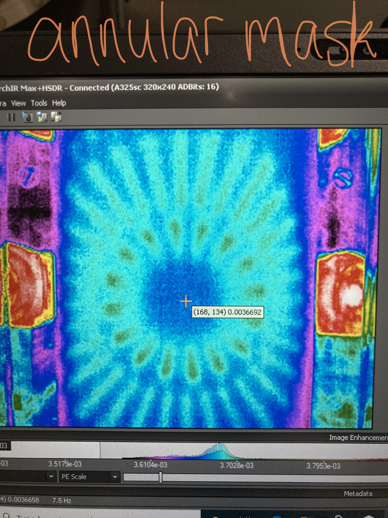
The imagines attached are how we have left the masks and alignment. Note: what appeared to be the FLIR no-mask alignment changed ALOT when the fan was on and panels removed which threw us off - probably as the FLIR was cooling unevenly and the beam is large. These images were taken with enclosure doors closed and fan off.
I have updated the distances spreadsheet with the new distances. This has been added to T2200035. Photos of the layout are also attached.
| Real Beam Path | Imaging Path | ||
| Masks to f=23" lens | 23" | Masks to f=10" lens | 11" |
| f=23" lens to CPx | 658" | f=10" lens to FLIR | 95" |
The f=23" lens in the main path is labeled LX-20B0-Z-ET8.0 PL/CX 23.00" FL. In the imaging path, IMG L1 f=10" is labeled as LX-20A0-Z-ET8.0 PL/CX 10.00" FL, this agrees with measured focal length using the visible LVEA ceiling lights of ~8".