J. Oberling, J. Driggers, C. Cahillane
Today we measured TFs for the PSL stabilization subsystems (PMC, FSS, ISS), and set their gains for the correct UGFs. To start, Jenne and I, with assistance from Marc (Thank You!!!), put together a couple of ~25' long BNC cables so we could take FSS TFs from outside of the enclosure; we also used 1 ~25' long, pre-built BNC cable, for a total of 3 new cables. Recall that we cannot take the TTFSS out of the enclosure due to cable length limits (if the cables are too long, the phase margin suffers and could make the control loop unstable). I ran into the enclosure and we pulled the new cables inside and plugged them into the TTFSS. The cables are labeled as follows:
- FSS TF IN1
- Plugged into IN1 on the TTFSS
- FSS TF IN2
- Plugged into IN2 on the TTFSS
- FSS TF EXC
- Plugged into Test2 on the TTFSS
This done, the enclosure was put back into Science mode, and the beam alignment into the PMC and the FSS RefCav was tweaked in advance of the TF measurements. Craig has the TF data on his laptop, but I took pictures of the TFs for quick posting to the alog. We started with the PMC, then the ISS, then the FSS. Results:
- PMC
- Gain: 7 dB
- UGF: ~1 kHz
- Phase margin: ~50.5°
- ISS
- Gain: 5 dB
- UGF: ~33 kHz
- Phase margin: ~41°
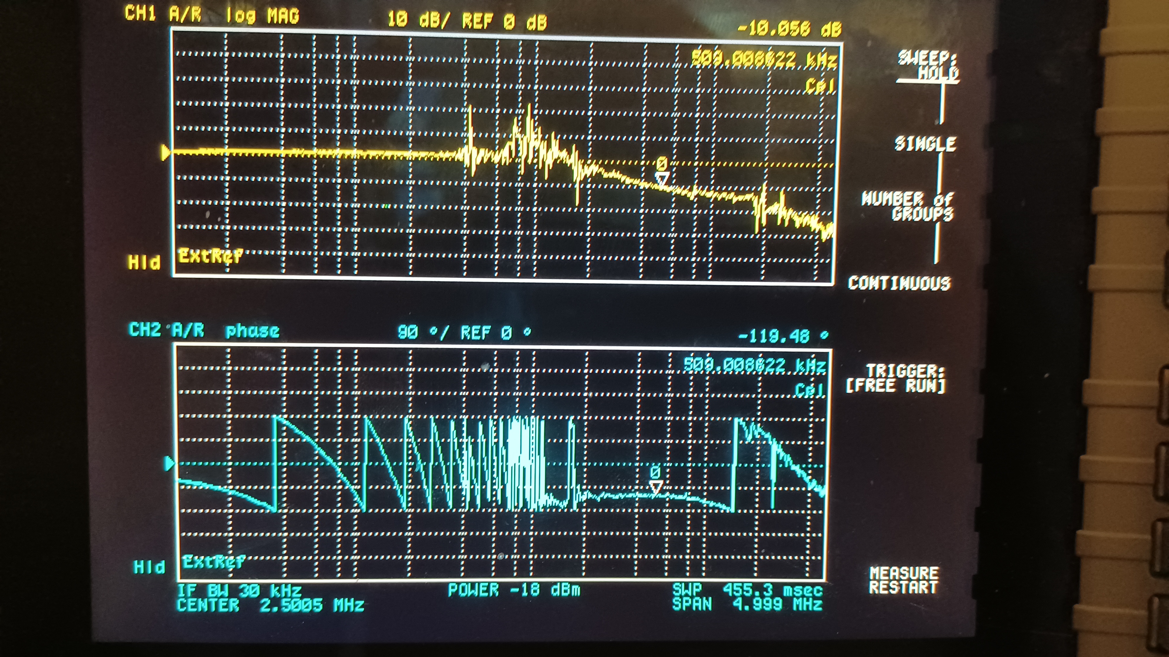
- FSS
- Common Gain: 20 dB
- UGF: ~510 kHz
- Phase margin: ~60.5°
It should be noted that we will likely have to revisit the FSS TF measurements as the RefCav TPD is now maxing out around 0.56 V, versus the 0.7 V it was at upon initial recovery (recall that we now have an ND filter in front of the RefCav TPD, as the increase in laser power resulted in an increase in RefCav TPD, to the point we were saturating the PD; this can be changed if more TPD voltage is needed for whatever reason). Since we are now keeping the enclosure in Science mode with the new laser running, the temperature has come to a new equilibrium of ~73 °F. When the FSS was originally recovered back in December 2021 we had the enclosure temperature at a somewhat more comfortable 70 °F. We have observed temperature differences like this causing misalignments in the FSS path in the past, so we will likely revisit the FSS path alignment to max the RefCav TPD; once we do this we will have to re-measure the FSS TF and likely change the gains again. In addition, we have not measured the FSS Crossover yet, because, being honest, I don't remember how to do it (last measurement was back in 2019, so it's been a minute). I'm currently looking into how to measure the crossover, once I figure that out we'll measure it and set the FSS Fast Gain appropriately. For now, to keep the EOM from being driven so hard (it was being fed close to 12V, which is way high), I set the FSS Fast gain to 13 dB (from our arbitrarily-chosen initial value of -5 dB), which has the EOM voltage down around 1V. All changes were accepted in SDF.


Data for these measurements was recorded here: https://git.ligo.org/aligo_commissioning/psl_measurements

Instructions and code for how to take the GPIB measurements are there as well.

We also measured the IMC OLG, we've left it at around 60 kHz UGF.

The FSS OLG measurement has been adjusted up by 10 dB to account for the -10 dB done in the TTFSS setup.
