Dhruva, Sheila, Daniel, Vicky
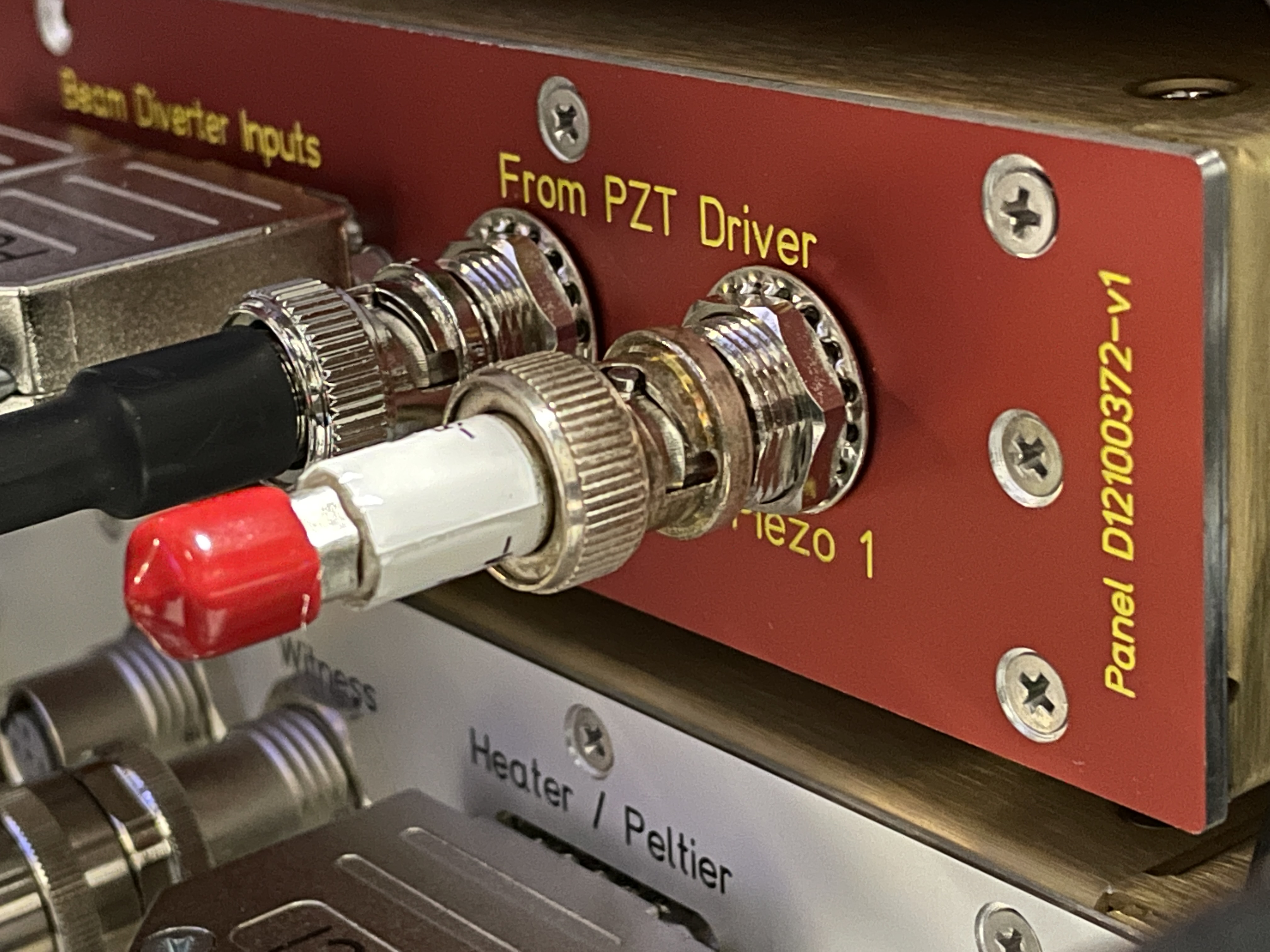
Measured OPO CMB transfer functions today with an SR785 at the sqz racks. See attached photos for OPO CMB transfer functions for feedback to OPO PZT1 and PZT2 (where pzt2 likely drives the curved mirror). For these measurements, we used a green pump power of ~8mW into the fiber on sqzt0.
Important things:
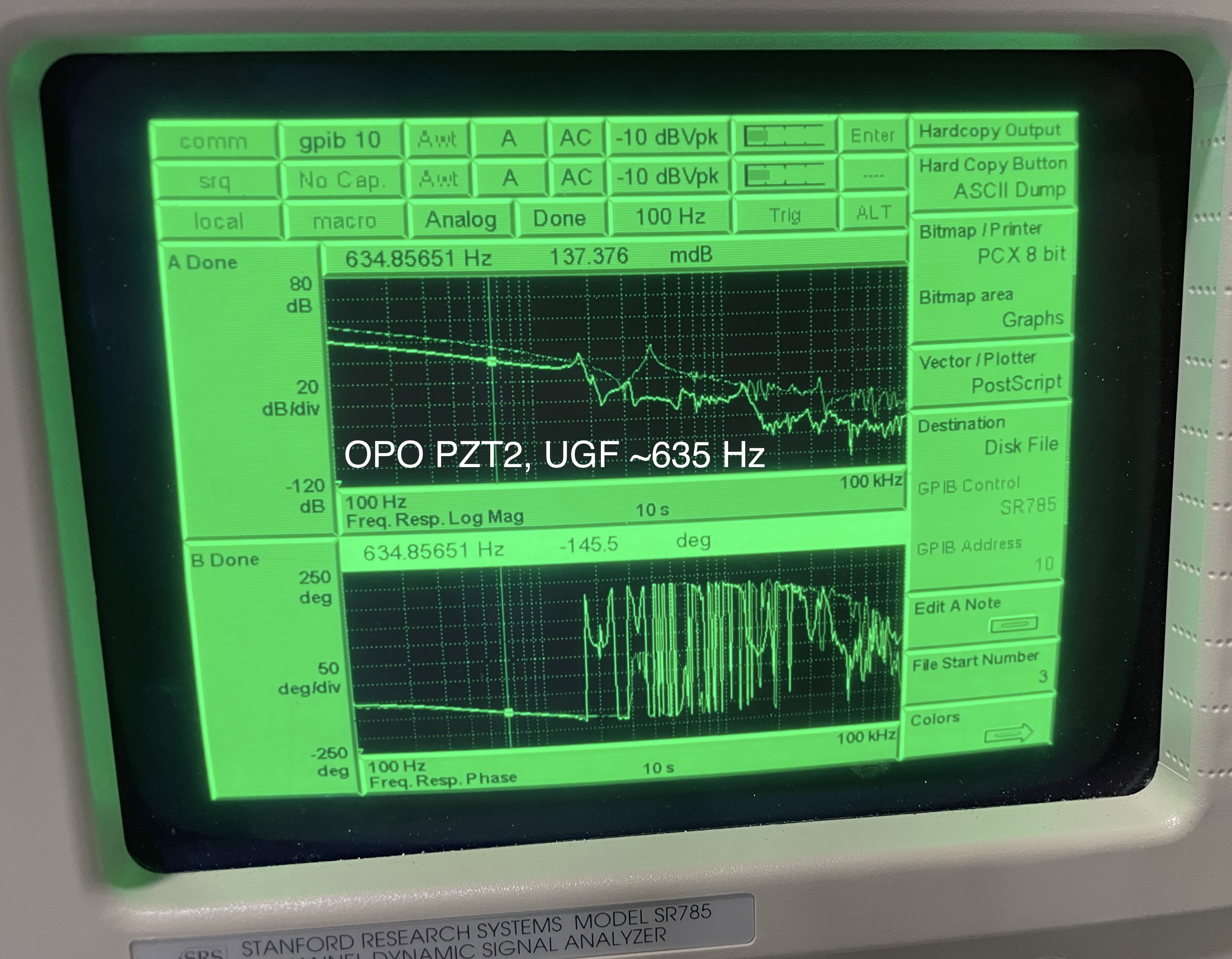
1) Compared to ~O3 (see Nutsinee alog 53009, Nov. 2019) where OPO loop had ~1.7kHz UGF, both opo piezos now (pzt1 ugf ~ 1.3kHz, pzt2 ugf ~ 635Hz) seem to have lower bandwidths. TFs both taken with no boosts, no "filters", and slow compensation "on".
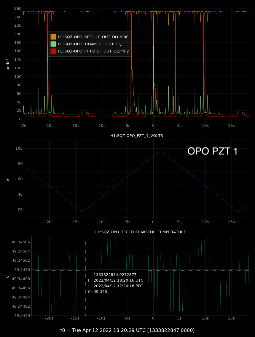
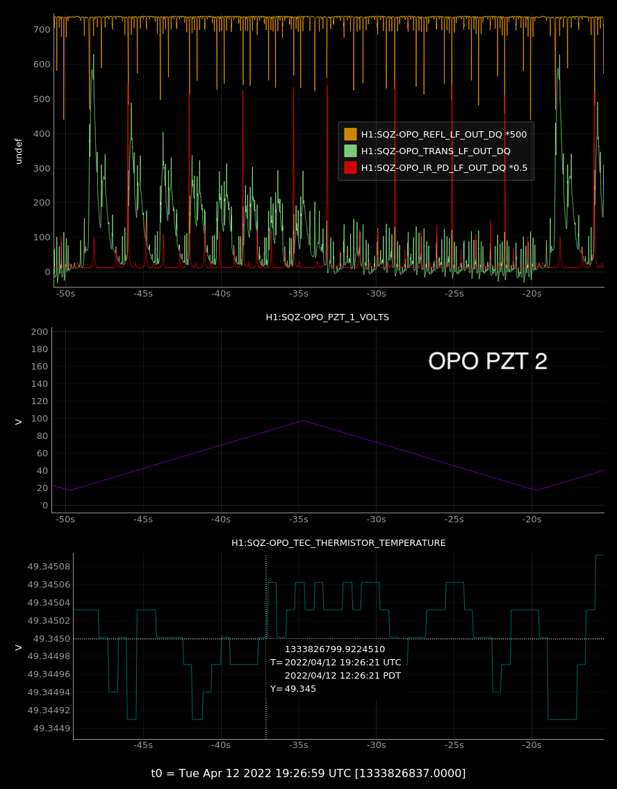
2) As with alog 61267, PZT 2 sweeps with much more displacement range than PZT 1 (see ndscopes attached: for the sweep range, PZT 2 has ~4 IR resonances; PZT 1 has ~1 IR resonance). The increased range of PZT2 is also noticeable in the OPO CMB, where the common gain decreased from -5dB to -25dB for pzt2. However, we seem to still have the same issue described in 61267, where scanning PZT 2 leads to cavity misalignents; can also see this from the medm screenshots. So, we will continue to lock the OPO using PZT1 although it has less scan range than PZT2, which affects the cavity alignment too much. Most ideal situation would be drive PZT2, but this requires re-aligning green pump input to the opo cavity to maintain alignment while scanning (ie redo from 61267).
Also done today was an attempt at non-linear gain (NLG) optimization via translating the crystal position. We started with an NLG ~ 3, at OPO TEC = 35.72 C, and 8.2mW of green pump power into the fiber. We didn't get the computer to drive the crystal position ("oven" connector) at all, so we will try again tomorrow. Additionally, the CLF 2F photodetector, and clf_trig_diode are all working now, though will need re-alignment in laser hazard.
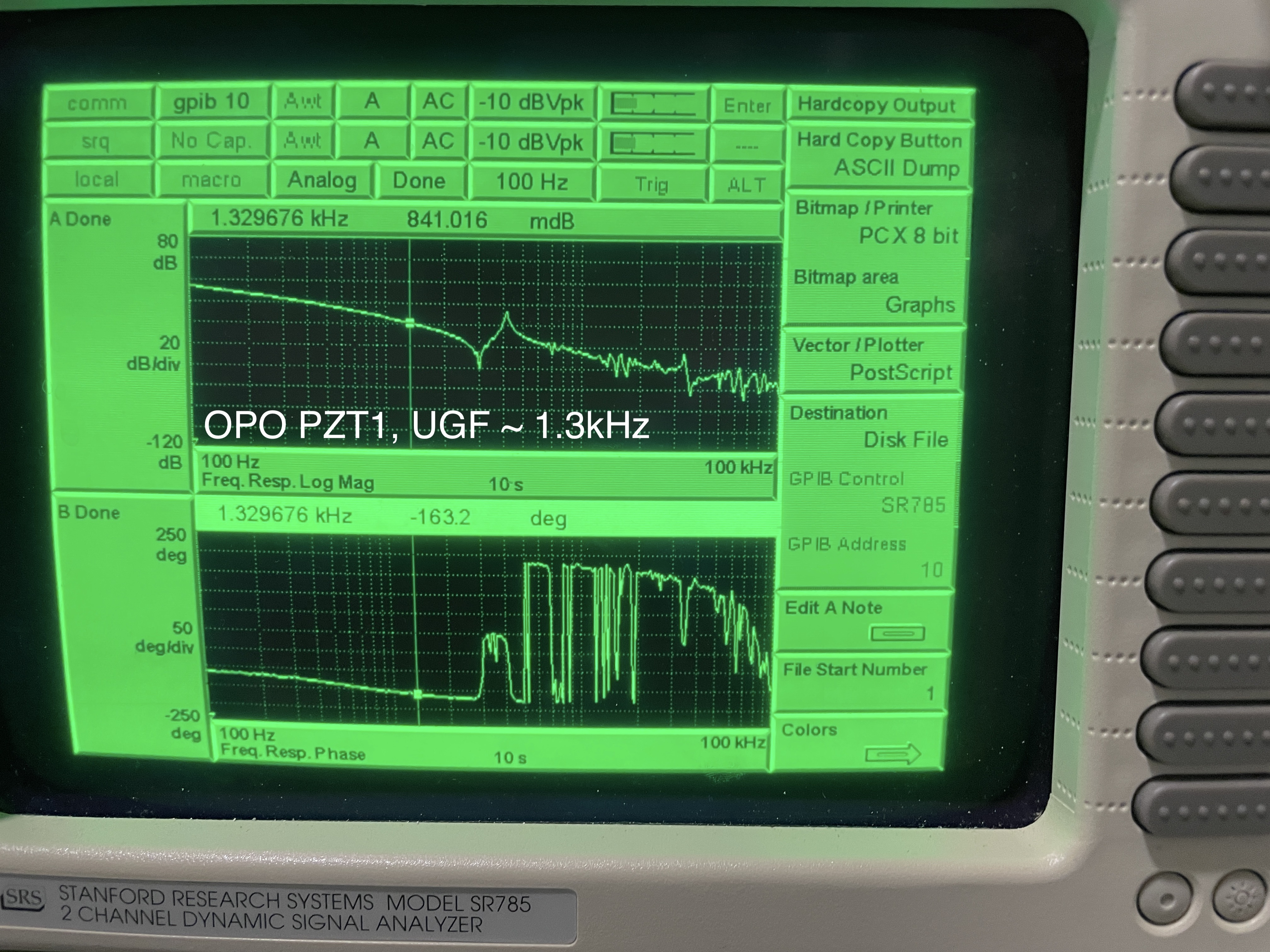
The lack of phase margin is due to the effect of the 400Hz pole in the PZT driver, which I forgot about. The required compensation for this loop is the 4Hz/400Hz "boost" in the slow path and not the 4Hz pole compensation filter.
Is the length-to-angle coupling really worse for PZT2, or is it just the fact that it has more range? PZT2 may be usable if we restrict its drive range to the "good" interval.