I modified the BSC-ISI master model to introduce the sensor correction path from the ground instrument (STS-2) to the stage 1 of the ISI. I added the 9 STS-2 inputs (3 signals per STS-2 and 3 STS-2s at the corner station). Now, 50 sensors signals feed to the BSC-ISI models.
The input filters of the STS are named: IFO:ISI-CHAMBER_ST1_GNDSTSINF_Group_DOF. In the existing stage 1 sensor correction block (the block was created to perform the sensor correction using the L4Cs of the HEPI), I added to the filters names dealing with the HEPI L4C the prefix HPI_L4C.
In this block, I also added filters (FIR and IIR) for the sensor correction path using the STS-2s. The prefix used for these filters is GND_STS. I integrated in the Master overview screen the STS and modified the stage 1 sensor correction path. A dozen of the screens were also created. While I was modifying the model, I also increased the sample rate of the excitation channels to 4K. I only installed the new model on ISI-BSC6.
I started to work on the Version 3 of the commissioning scripts to consider these changes in the models. For the moment, I have upgraded the “Routine 0” of the scripts to introduce the calibration filters of the STS-2. The STS-2 signals are added to the CPS after passing through a series of filters. I created a routine to load the IIR and FIR filters used to create the high pass filter. The companion filters ISI_4k_FIR_companion_filters_GND_STS_20130509.mat in userapps/release/isi/common/filterfiles. These filters are only usable for the ground path sensor correction (Different names for HEPI L4C)
I also created a routine to compute and load the “Match” filters used to correct the calibration errors between the STS-s2s, the T240s and the CPSs. The CPSs are used as reference. The reference is the simulated Cartesian transfer functions with the ISI damped.
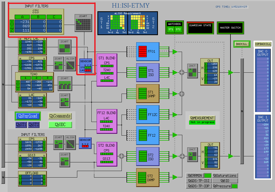
In attachment, you can find the new overview screen (BSC-ISI_Overview.png). The modifications are visible are in the red box.
After measuring transfer functions from the STS-2 to the T240s (ISI damped) and using the damped transfer functions, I computed the match filters for the ground path sensor correction. The match filters are just gains close to 1 (+/- 3% correction).
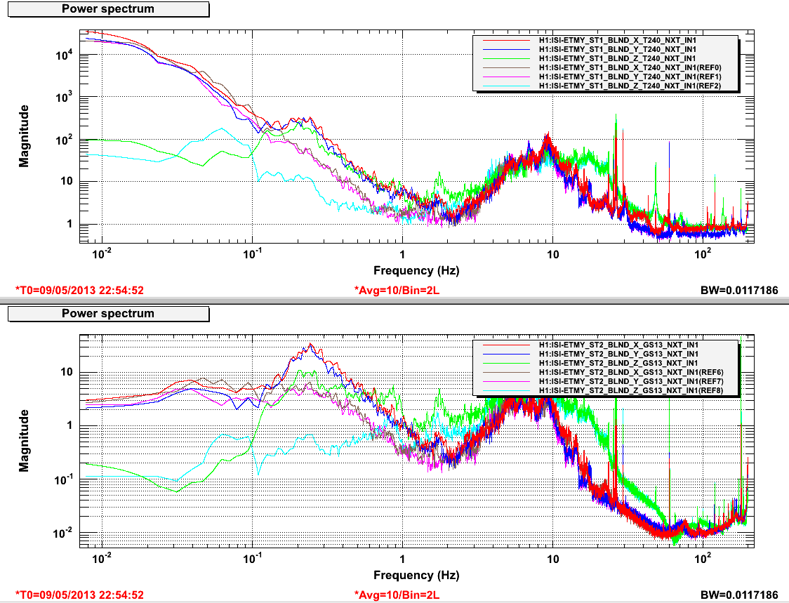
I measured some spectra (calibrated in nm/s for the T240 and nm/s for the GS13 above 1Hz) with and without the sensor correction (STS-2). In the figure H1_ISI_ETMY_Sensor_Correction_20130509_155200.png, spectra are measured in the following configuration:
- High gain on L4Cs and GS13s
- On stage 1, blend at 250mHz with the T240s in the super sensor in X, Y and 750mhz without the T240s in Z, Rx, Ry, Rz.
- On stage 2, blend at 250mHz in X, Y and 750mHz on Z, Rx, Ry, Rz.
- UGF: 15Hz for all DOFs
- The plots with the "ref" label indicates that the sensor correction was engaged.
Results are pretty good especially in the Z direction (the blend frequency is 750mHz whereas it is 250mHz in the X and Y directions). Tomorrow, I will increase the UGFs of the isolation filters on the 2 stages.