jeffrey.kissel@LIGO.ORG - posted 17:58, Thursday 09 June 2022 (63520)
CAL-CS_DELTAL_EXTERNAL Still Has Systematic Error, Even though Measurements Agree (Roughly) with pyDARM Model
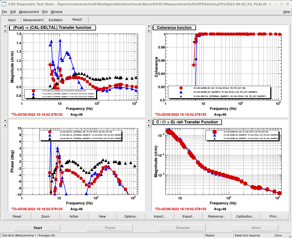
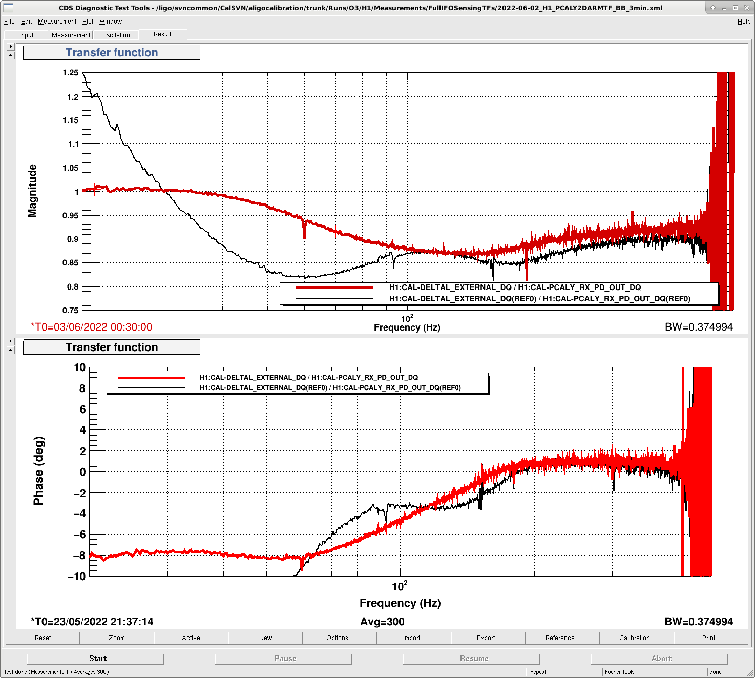
J. Kissel,

I'm continuing the investigation as to why transfer functions between PCAL drive and H1:CAL-DELTAL_EXTERNAL_DQ response indicate that there's still systematic error (see DTT template reports of it in LHO:63506).

After seeing the current level of agreement was good between the 2021 model parameters currently installed that are creating DELTAL_EXTERNAL and
   - the sensing function measurements LHO:63429 and
   - the actuation function measurements LHO:63450,
the current guess going into this was that "it must be that the transfer function that lives in the DTT template" which corrects for
   (A) the DELTAL_EXTERNAL_WHITEN filter, and
   (B) the short-falls of the front-end in its ability to capture super-Nyqist zeros and poles

I know it's hard to intuit (B), but neglecting super-Nyquist poles screws up the phase of 1/C at the DARM UGF by a non-negligble few degrees, which screws up the relationship between A and 1/C as they're added coherently together, which counter-intuitively creating wiggles around / as-low-as the 50 to 200 Hz region because the sum of 1/C + A is not well phase matched.

I no longer think this is the case -- my suspicion now lies
   - on the relative delay between A and C that we install for DELTAL_EXTERNAL to approximate (B), and
   - the optical gain / cavity pole in the CS_DARM_ERR bank, which houses 1/C.
but I wanted to get this aLOG in before I head out for a longer-than-normal weekend and get sucked into activities related to the HAM1 vent next week.

As such, a resurrected the infrastructure to export the raw H1:CAL-DELTAL_EXTERNAL_DQ / H1:CAL-PCALY_RX_PD_OUT_DQ transfer function, and do the anti-whitening and "high-frequency" corrections, using the math outlined in Section I of T1900169, culminating in Eq. 40.

This is delightfully easy to do using the new pydarm system, and I've done so with the script
    https://git.ligo.org/Calibration/ifo/-/blob/main/scripts/fullifosyserrtfs/process_fulliforesponsetf_SS_20220602.py


Doing so required me to update the 20220527 model parameter set,
    pydarm_modelparams_PostO3_H1_20220527.ini

(the updated 20220527 model parameter set is now committed the revision number indicated by the git-repo hash ff02797e717edfb65dd06432e7b56a5db8f4dc81, or simply ff02797e)

The update to the model parameter set was to fix the pointers to now newly exported CAL-CS filter bank transfer functions
    /ligo/svncommon/CalSVN/aligocalibration/trunk/Runs/O3/H1/Measurements/Foton/
        2022-06-08_H1CALCS_8_CLK_DELAY.txt                       # Hand created transfer function of the phase loss from eight 16 kHz clock cycle delay by E. Goetz, a copy of ${pydarm}/test/H1CALCS_8_CLK_DELAY.txt
        2022-06-08_H1CALCS_ActuationFunction_Foton_L1_tf.txt     # An export of the active filters in the H1:CAL-CS_DARM_ANALOG_ETMX_L1 filter bank, from f = 0.01 to 10000 Hz, 10001 points
        2022-06-08_H1CALCS_ActuationFunction_Foton_L2_tf.txt     # An export of the active filters in the H1:CAL-CS_DARM_ANALOG_ETMX_L2 filter bank, from f = 0.01 to 10000 Hz, 10001 points
        2022-06-08_H1CALCS_ActuationFunction_Foton_L3_tf.txt     # An export of the active filters in the H1:CAL-CS_DARM_ANALOG_ETMX_L3 filter bank, from f = 0.01 to 10000 Hz, 10001 points
        2022-06-08_H1CALCS_DELTALEXT_WhiteningFilter_Foton_tf.txt  # An export of FM2 "0.3^6:30^6" whitening filter in H1:CAL-CS_DARM_DELTAL_EXTERNAL_WHITEN, from f = 0.01 to 10000 Hz, 1001 points

which are needed to compute (B).

The results are attached.
    - First Attachment: This is a demonstration of (B) from above, and the result of the math from T1900169. Be aware: I'm plotting "\eta_R," which is the corrective, multiplicative transfer function that one multiplies H1:CAL-DELTAL_EXTERNAL_DQ by in order to get it closer to PCAL, which we believe is a better estimate of the true differential arm displacement. Thus, this plot is the inverse of the raw H1:CAL-DELTAL_EXTERNAL_DQ / H1:CAL-PCALY_RX_PD_OUT_DQ transfer function shown in the DTT templates. We use this convention of display because there's one less thing that you need to invert mentality in order to get the thing you actually want which is "how will this change the ASD of DELTAL EXTERNAL and affect our range?" So, saying in words that this report of the systematic error will do --
        where \eta_R is greater than 1 above 60 Hz, the sensitivity reported by DELTAL_EXTERNAL is *over-estimating* the sensitivity, and the true sensitivity is less (higher ASD) and our true inspiral range is worse, and
        where \eta_R is less than 1 below 60 Hz, the reported bu DELTAL_EXTERNAL is *under-estimating* the sensitivity, and the true sensitivity is more (lower ASD), making our inspiral range better.
    Unfortunately, because of the dependence of the integrand of our range on f^(7/6), it's difficult at best to intuit the over all change in range will be without a script to do the math for us.

    - Second Attachement: Just shows that the broad-band injection agrees with the swept sign measurement.

Discussion
 On can clearly see in the Second Attachment that
   - Doing the (B) corrections "offline" outside of the template's old version of that transfer function doesn't make that much of a difference, and looks like DTT versions of the swept sine TF and the broad-band TF.
   - this metric still reports an asymptote to ~10% systematic error at high frequency, and a 10-20% wiggle between 20 and 400 Hz.
I have no choice but to conclude that something's wrong with the CAL-CS model, and there really still is systematic error in DELTAL_EXTERNAL

So ... what could it be?
   (1) As discussed in the text surrounding Eqs. 12 through 18 of T1900169, we approximate the transfer function (B) discussed above, and in Eq. 40, by accepting that DELTAL_EXTERNAL will have an approximate delay of \delta C ~ 90 [usec], and adding the *sum* of the \delta A and \delta C delays to A, converted into 16 kHz clock cycles into the H1:CAL-CS_DARM_CTRL_DELAY_CYCLES channel. I find this visually explained best in the diagram of an old 2015 aLOG LHO:22117.
       - Of course, the *value* of this delay depends on the transfer functions of \delta C and \delta A -- and the approximation that those transfer functions can be represented as phase loss and no magnitude change below Nyquist, and therefore can be treated as "just delays" -- depends on the current super-Nyquist poles that are present.
       - The predominant *change* is in \delta C, since we have a brand new OMC DCPD electronics, which have many more poles all as low as 10-11 kHz.
     So -- I think we need to have look at whether this H1:CAL-CS_DARM_CTRL_DELAY_CYCLES should still be 8.
       -  Even worse though, recall that using more than 7 clock cycles of delay has given us trouble in the past -- see LHO:48620, so we'll have to dig up that old laundry too.
       - But the first step is to convert old pydarm scripts,
  ^/trunk/Runs/O3/H1/Scripts/CALCS_FE/compute_relativedelay_AvsC_20210417.py

         to the new infrastructure that produces plots like 2021-04-17_H1_AvsC_RelativeDelay.pdf to compute what that new delay will be with all the five new 10 kHz OMC DCPD electronics.

    (2) I also just need to look at the optical gain in the front-end. In LHO:63429, the gold trace in the upper right magnitude residual of the first page of the model_vs_measurement quad plot shows that the measurement has a 2% discrepancy with the 2021 model that's currently installed. That disagrees with the ~10% that PCAL reports from the DELTAL / PCAL transfer function.

So yeah ... more modeling to do to try to understand what's going on and to provide recommendations.
Non-image files attached to this report
