jeffrey.kissel@LIGO.ORG - posted 14:26, Friday 22 July 2022 - last comment - 18:10, Monday 25 July 2022(64114)
Reverting ECR E1400369, Decreasing HSTS M3 Coil Driver Strength, Should Improve DAC Noise Injection (if Damping Loops Sensor Noise Re-injection is also Improved)
J. Kissel [inspired by questions from A. Effler, J. Driggers, S. Dwyer, P. Fritschel, and D. Sigg]

Several folks have ask me over the years to remind them of the coil driver actuation strength situation on the recycling cavity HSTSs, and with the recent successes in revisiting these parts of the suspension control design and the fact that these are noise limiting noise sources in DARM, it's time I get my act together and post the demonstrative plots I quickly made in the pandemic times while I was working to improve the HSTS damping loop design.

As a reminder, in ~2014, when we were still struggling to get DRMI to acquire quickly, guest stars at LHO suggest we increase the actuation range on a lot of H1's HSTSs (ECRs E1200931 and E1400369, with me parroting those guest star wishes in the presentation G1401125). In 2017, we re-discovered all this, and I inventoried where we ended up as each site decided for themselves what they wanted installed (copied and now updated from LHO:32021):


At LHO the configuration is
    Driver Configuration            Optics
    No modified TACQ Drivers        MC1, MC3
    M2 modified, M3 not modified    MC2
    M2 and M3 modified              PRM, PR2, SRM, SR2

At LLO, the configuration is
    Driver Configuration            Optics
    No modified TACQ Drivers        MC1, MC3,
    M2 modified, M3 not modified    MC2, PRM, SR2, SRM, PR2
    M2 and M3 modified       none


In 2021, Anamaria and I found some time to try to install at least some DOFs of my "Level 2" Damping Loop design from G1401290, but due to long-standing issues with my models disagreeing with reality in terms of over all gain -- and a flawed roll filter design -- they didn't work (see the "to be aLOGged" section of G2100769). However, the L, P and Y loop design *models* are still solid, assuming we can just scale the overall gain to match reality, as I've found I've been needing to do the other confirmed successes with the HXDS, OMCS, and HTTS (see LHO:62837, LHO:60049, and LHO:63656).

So, assuming the L, P, and Y noise budgets are accurate, I predicted the actuator noise difference between the L1 and H1 driver configurations in the attached plots.
    - With both M2 and M3 driver stages modified, i.e. the LHO configuration dampingfilters_HSTS_H1SR2_ImproveLPY_2021-02-22_totalbudget_LPY.pdf.

    - With only the M2 stage modified, i.e. the LLO configuration dampingfilters_HSTS_L1SR2_ImproveLPY_2021-02-22_totalbudget_LPY.pdf

By comparing the second and third pages, cne can see that -- assuming we improve the sensor-noise reinjection with the improved damping loop design -- H1's HSTS will be limited by DAC noise reinjection of the M3 stage above 10 Hz in pitch, and 6 Hz in yaw.
That being said, even in the LLO configuration, we'll still be limited by DAC noise, but that DAC noise will be lower.

I'll check what kinda of coil driver range we use during lock acquisition these days, to uber confirm, but I recommend we revert all PRM, PR2, SR2 SRM M3 coil drivers to the original actuation range of the original D0901047 design.
Non-image files attached to this report

Comments related to this report
Here's the DAC usage from PRM, PR2, SR2 and SRM M3 stages during the most recent lock acquisition.
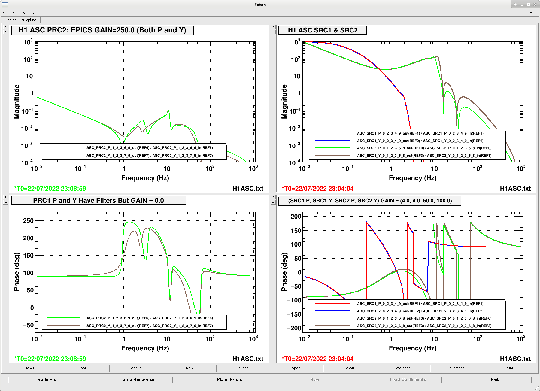
Recall, H1's control scheme:
Only PRC2, SRC1, and SRC2 are on in nominal low noise.
SRC2 is the higher bandwidth loop.
ASC Pitch Actuation Matrix:
PRC1 PRC2 SRC1 SRC2
1.00 PRM M3 (offloaded to M1, skipping M2)
1.00 PR2 M3 (offloaded to M1, skipping M2)
1.00 -7.60 SRM M3 (offloaded to M1, skipping M2)
0.00 1.00 SR2 M3 (offloaded to M1, skipping M2)
ASC Yaw Actuation Matrix:
PRC1 PRC2 SRC1 SRC2
1.00 PRM M3 (offloaded to M1, skipping M2)
1.00 PR2 M3 (offloaded to M1, skipping M2)
1.00 7.10 SRM M3 (offloaded to M1, skipping M2)
0.00 1.00 SR2 M3 (offloaded to M1, skipping M2)
I attach plots of the control filters for PRC2, SRC1, and SRC2, quoting the EPICs gain in the title of the plot; see 2022-07-22_H1ASC_PRCSRC_Filters.png.
We DO NOT apply any offset on any of the coils in effort avoid 18-bit DAC zero crossings. Worth considering, of course.
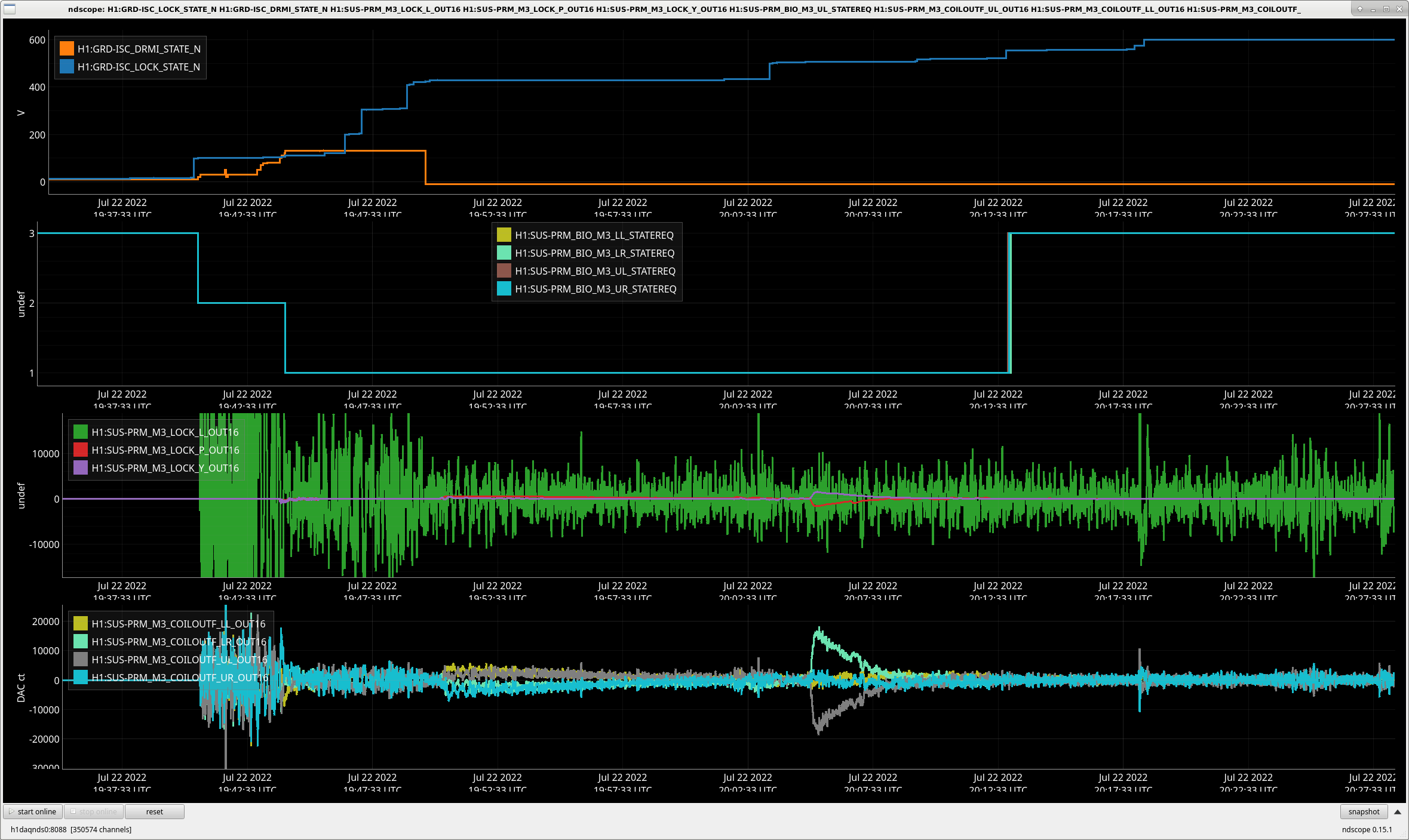
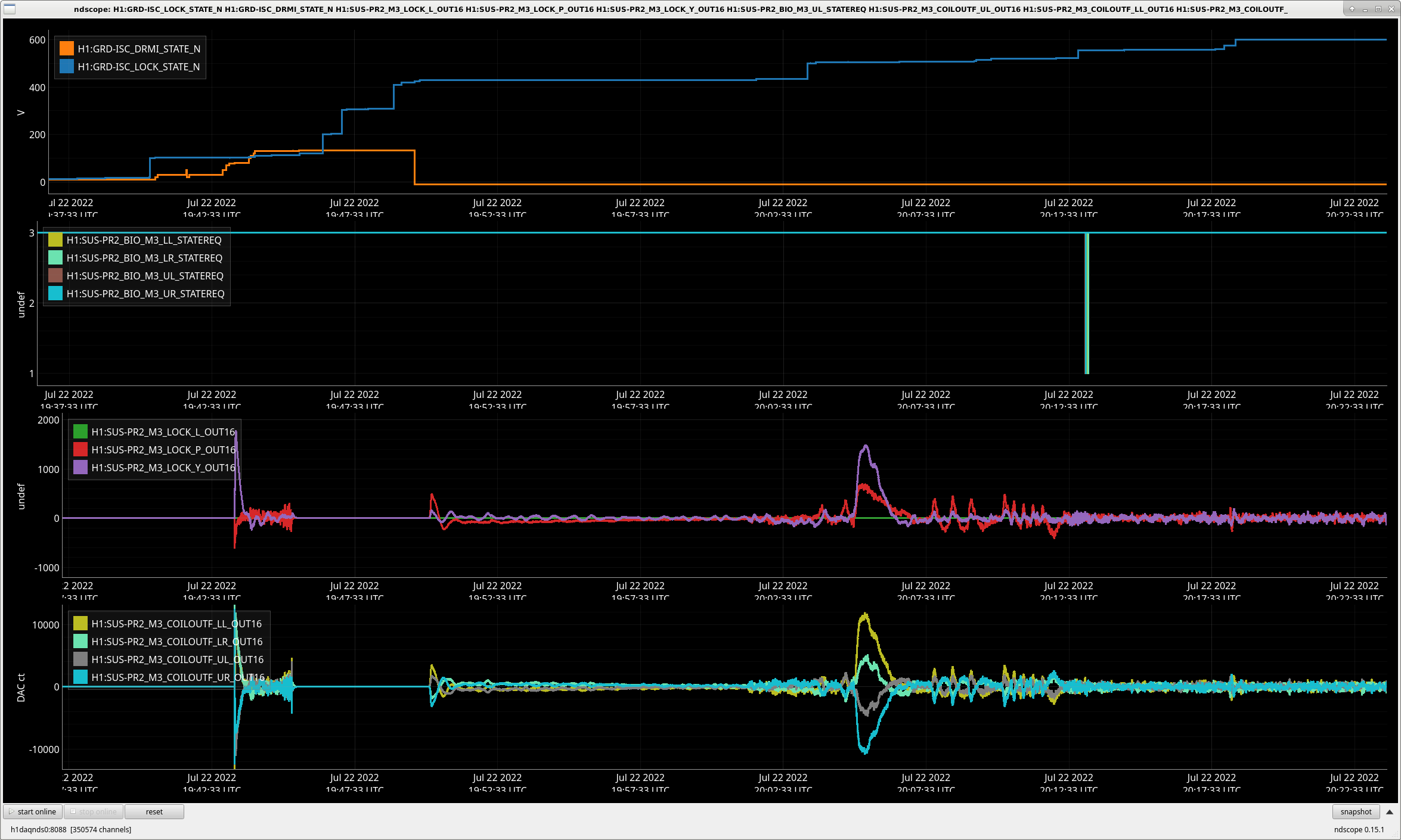
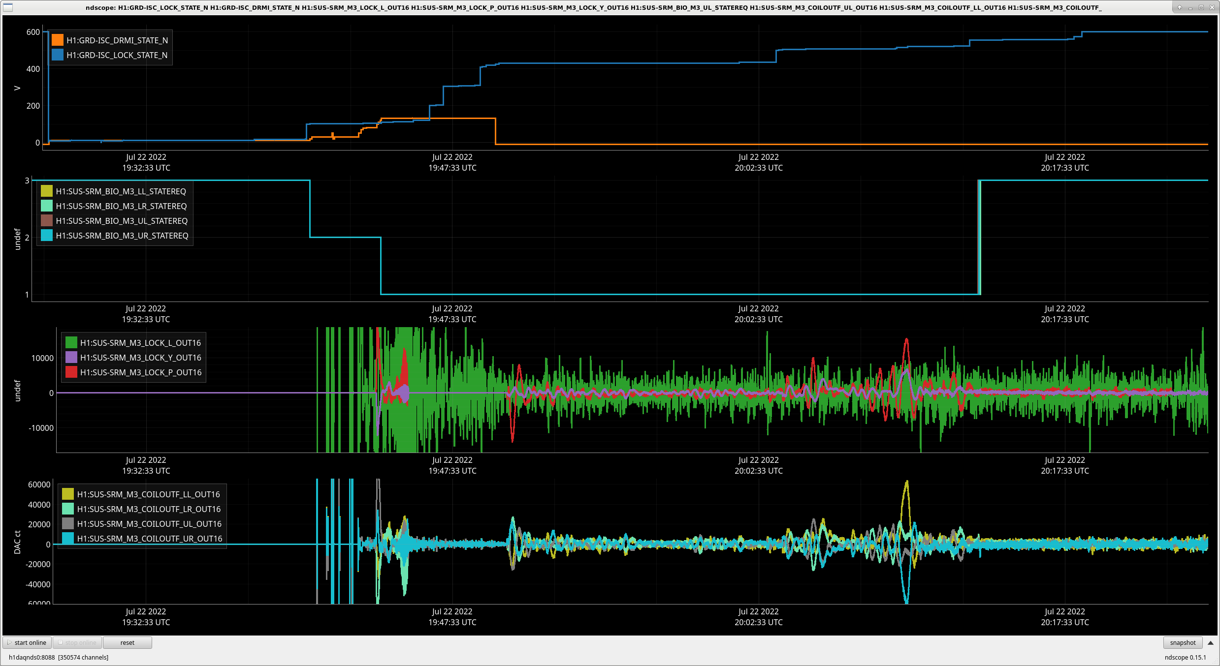
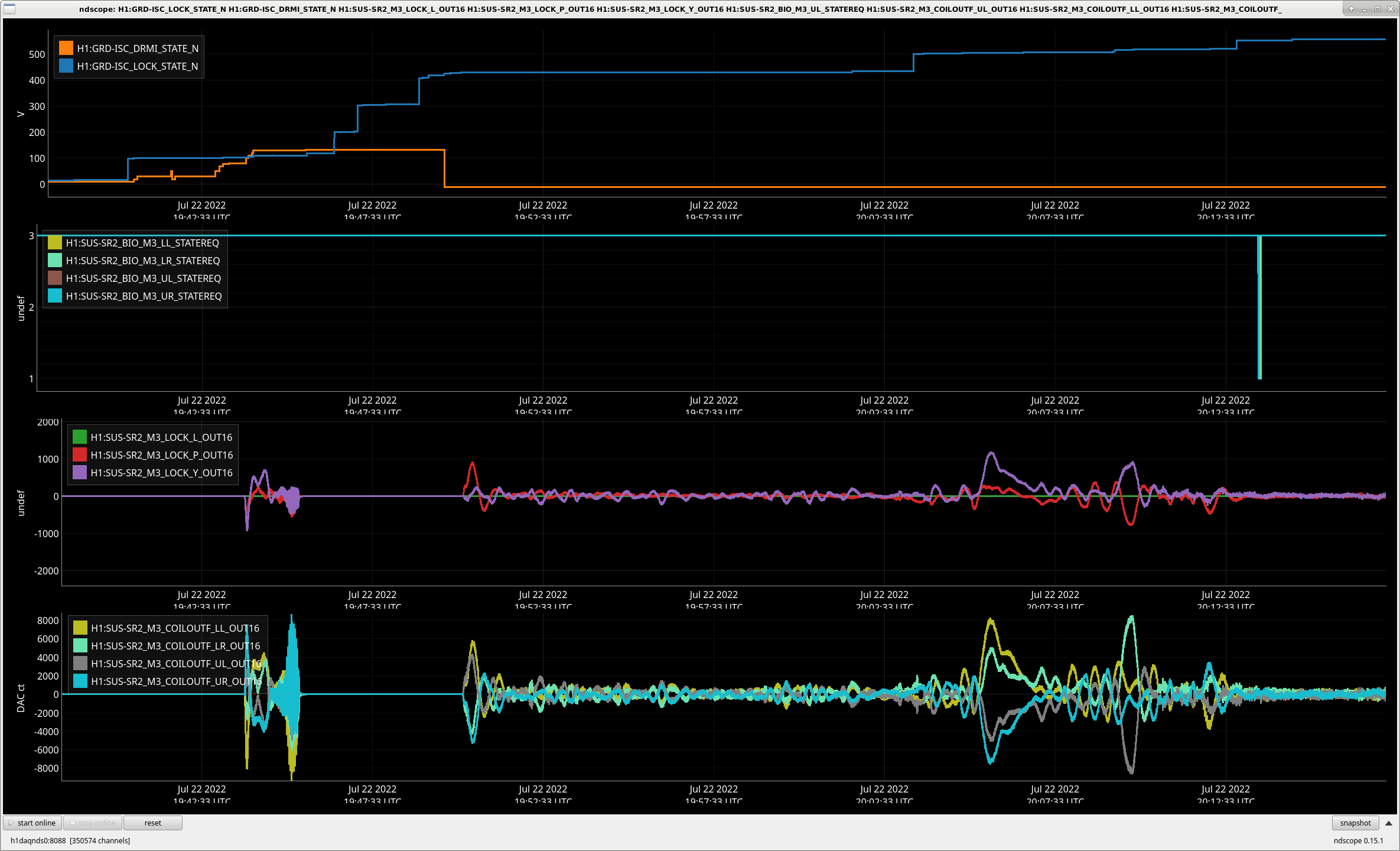
With this in mind, I show the trend of drive signal for all four optics.
In summary,
- During acquisition, PRM and SRM are switched to state 1, then once lock is acquired, they're switched to state 3
In a modified TACQ driver,
State 1 is essentially flat in frequency,
State 3 is a soft band stop (often, loosely called a low pass) between 0.5 and 500 Hz centered at 20 Hz.
- Interestingly, PR2 and SR2 are not switched out of state 3
- SRM M3 gets the vast majority of the high frequency drive signal, since it's the only actuator for SRC2, the high bandwidth loop
- PRM control maxes out at ~2.0e4 / 2^18 = 7.6% of its 18-bit DAC range.
- PR2 control maxes out at ~1.2e4 / 2^18 = 4.5% of its 18-bit DAC range.
- SRM control maxes out at ~6.0e4 / 2^18 = 22.8% of its 18-bit DAC range.
- SR2 control maxes out at ~0.8e4 / 2^18 - 3.0% of its 18-bit DAC range.
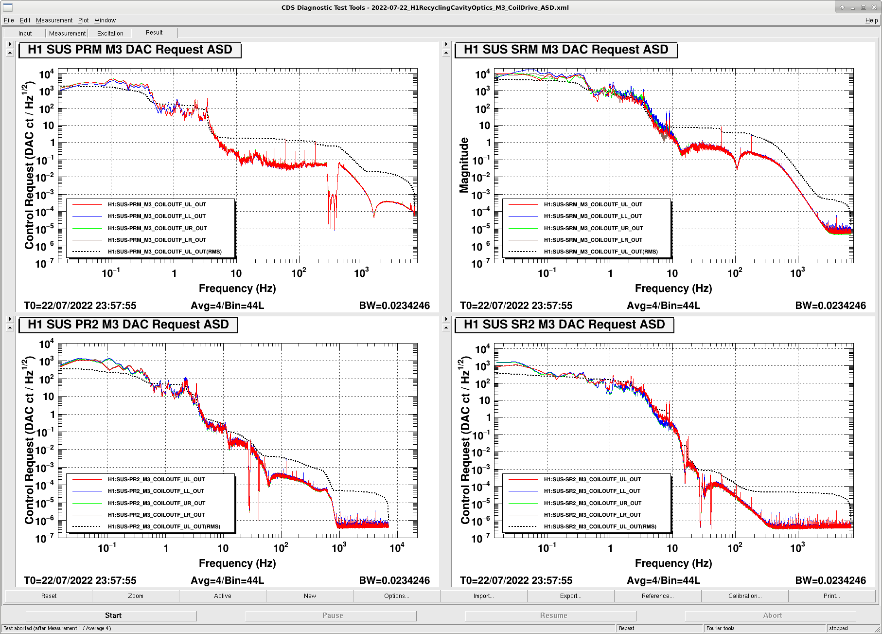
And finally, I attach an amplitude spectral desnity of the M3 DAC drives during nominal(ish) low noise. While this isn't helpful in defining how much range we'll need (lock acquisition should), it is informative regardless. I'm not sure where the cross-over for offloading to the M1 stage is, but in low noise, the RMS request is largest on SRM at a ~500 ct, and the rest of the SUS have lower.
If anyone wants to repeat these measurements (trends or ASDs) for future acquisition sequences, you may find templates here:
/ligo/home/jeffrey.kissel/Templates/DTT/2022-07-22_H1RecyclingCavityOptics_M3_CoilDrive_ASD.xml
/ligo/home/jeffrey.kissel/Templates/NDScope/
drmi_lock_coildriver_range_prm_m3.yaml
drmi_lock_coildriver_range_pr2_m3.yaml
drmi_lock_coildriver_range_srm_m3.yaml
drmi_lock_coildriver_range_sr2_m3.yaml
Happy hunting!
Images attached to this comment
Edit to the above comment: In my haste, I computed the "percentage of actuation range being used up with the current control request" by dividing the largest values seen in the last row of each trend plot by 2^18. However, this is 2^18 is the peak-to-peak range of the 18-bit DAC. The peak control request excursion should be compared against the peak range, +2^17 or -2^17.

    - PRM control maxes out at ~2.0e4 / 2^17 =  15.2% of its 18-bit DAC range.
    - PR2 control maxes out at ~1.2e4 / 2^17 =   9.2% of its 18-bit DAC range.
    - SRM control maxes out at ~6.0e4 / 2^17 =  45.8% of its 18-bit DAC range.
    - SR2 control maxes out at ~0.8e4 / 2^17 =   6.1% of its 18-bit DAC range.

Looking at these corrected numbers makes losing a "factor of 10" in actuation range less attractive superficially, but these trends are showing excursions that are quite slow -- arguably slower than should be requested of the M3 stage. Look again at the SRM M3 stage which is requesting the most range, bottom most, 4th panel, between 20:02 and 20:17 UTC.
The 3rd panel above it shows the ISC request that creates this request in the 4th panel. We see it's mostly pitch with some yaw. We can resolve the excursion between tick marks that are 15 minutes apart, which means that the request is really slow (low-frequency) -- maybe the ADS control signals?
This slow request should probably be offloaded to a higher stage, and makes me wonder what what frequency we've offloaded to M1, and/or how aggressive the high-pass is for the M3 control.

In other words, in order to improve the DAC noise injection by removing the factor of 10 in the coil driver, we may have to first tune-up our distribution of control to each stage of these suspensions. And again, driving ASC from M2 instead of M3, like L1 does, may be a part of that answer.