Sheila, Georgia, Dhruva, Robert
The first round of IR photos were swamped by light from the BOSEMs, so Sheila suggsted turning off the coil drivers on the platform. Even with the BOSEMs off, it was a little tricky seeing beam spots that came and went as the beam diverter was opened and closed. With a camera mount on the viewport, I was able to take open/closed pictures that could be precisely overlapped. The first and second pages of Fig1 show photos for diverter closed and open; there are 3 bright spots that are only there when the diverter is open. It is best to view with a pdf viewer that can flip back and forth between pages rather than scroll. The second two pages of the figure shows the "open " picture zoomed into the region with the 3 spots, along with a well lit picture that overlaps with it for optic identification. In addition to the three bright spots, there are a couple of spots that are not as bright.

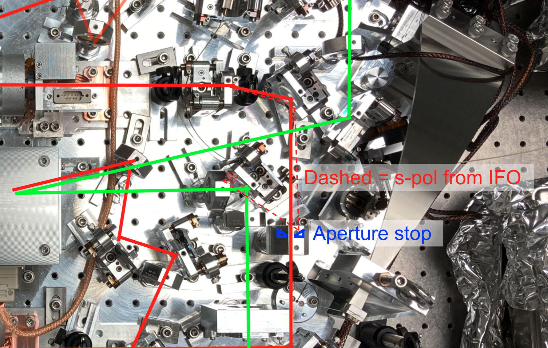
The bright spot in the upper right of Robert's image seems to be on B:PD1 (OFI rejected power PD, which is the one we were suspicous of).
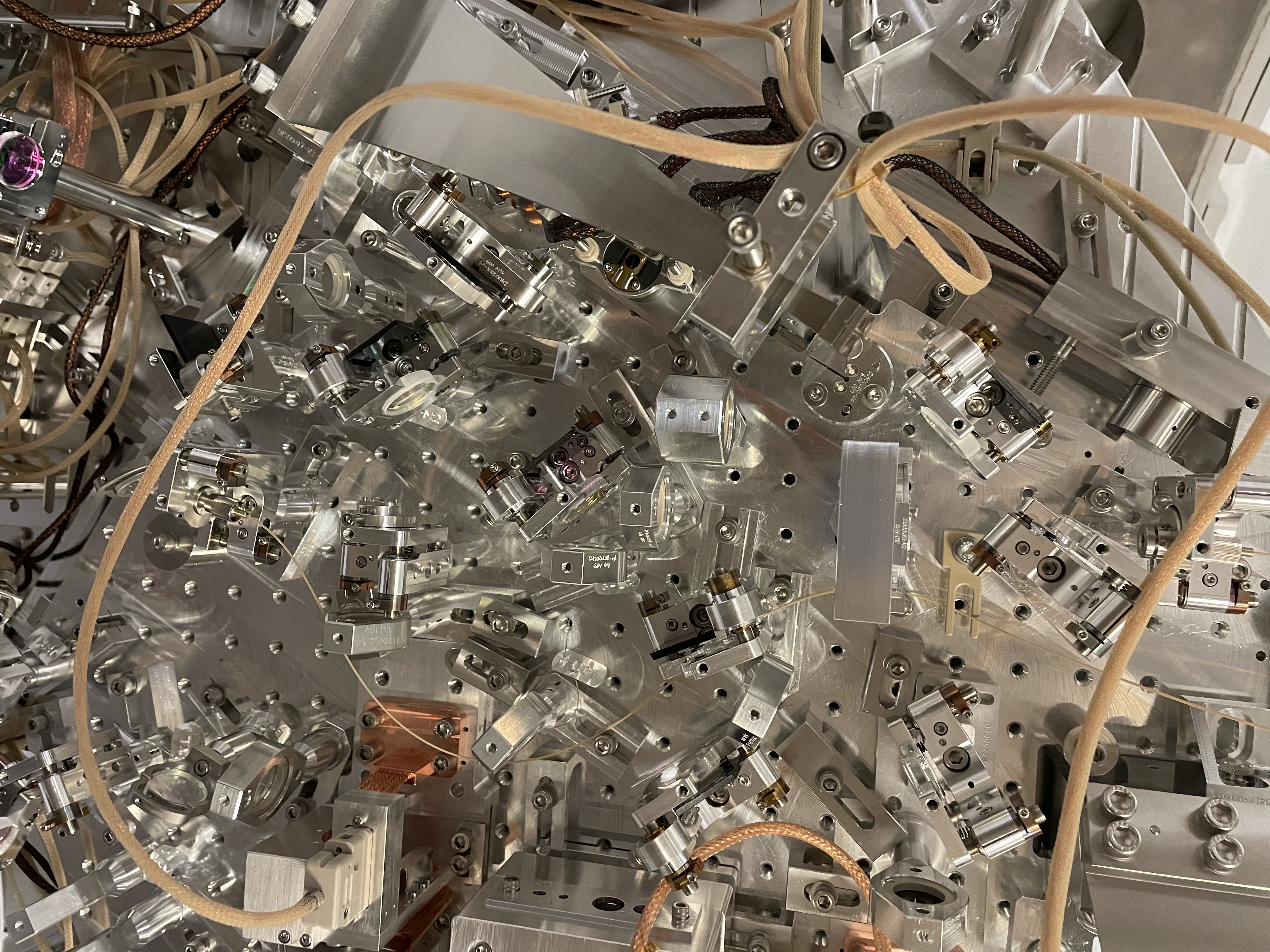
A photo that is helpful to identify the second (from the top) bright spot Robert identified is here: overhead VIP shot, the lens mount that has the bright spot on it is holding an aperture stop as shown here. The aperature stops aren't shown in the solidworks layout but the diagram on page 8 of T1900649 shows that this aperture stop is intended to catch the p pol beam from the IFO rejected by SFI2, (and a rejected beam from the polarizer for the input to SFI1, on the other side.)
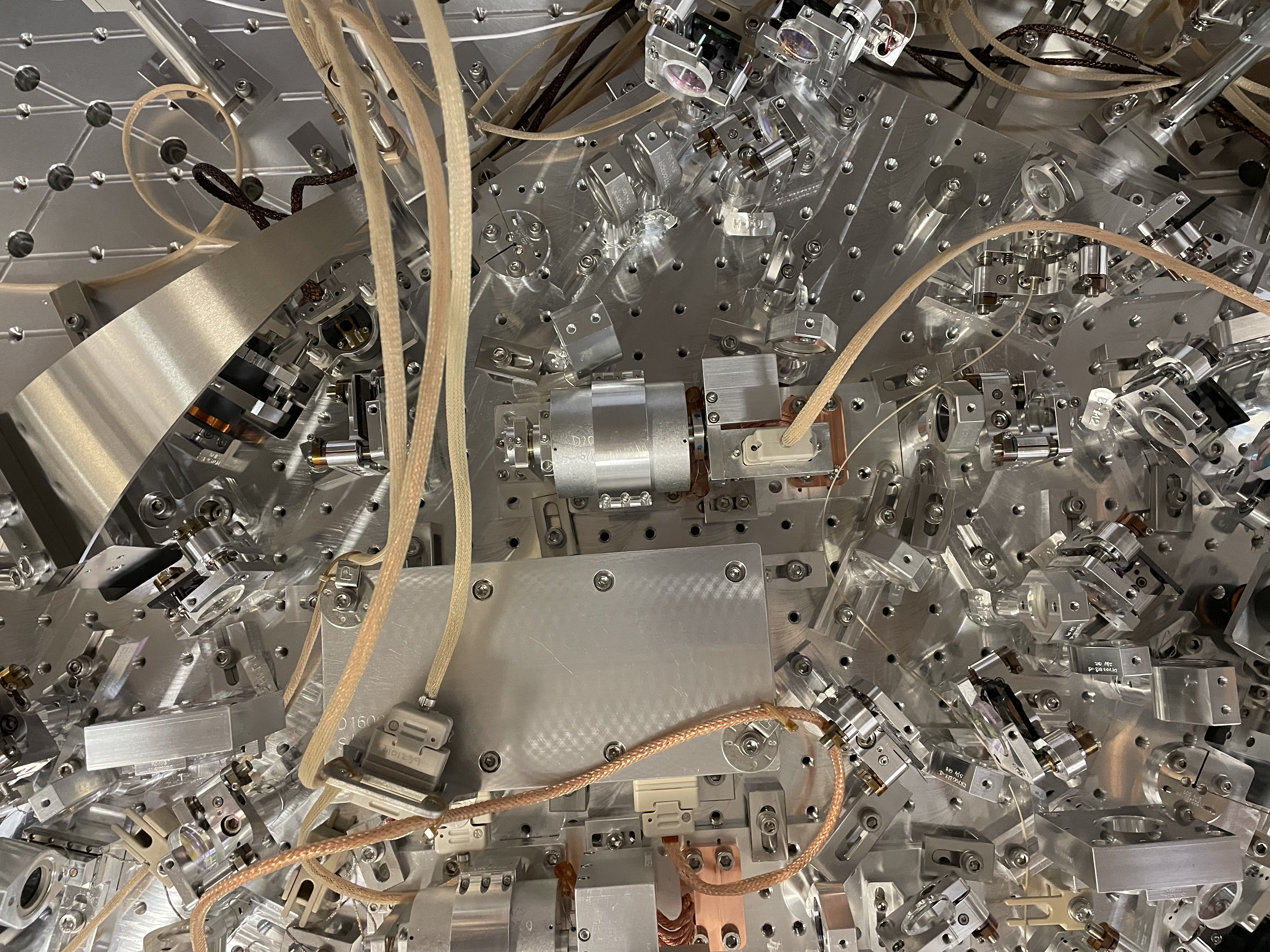
It is more difficult to understand how interferometer light would reach the third spot Robert identified, which seems to be on the edge of G:L1, G:M1, or less likely G:L2. These optics are labeled here but this photo shows that the as built arrangement is different than the layout with G:L1 moved upstream of G:M1. Another possibility is that the bright spot could be a beam clipping on the actuator for A:M2, but it is also hard to imagine a path for interferometer light to reach there.