Camilla, Robert
Suggested movement of OFI_PD_A (B:BD1): 2 mm up, no horizontal movement
When the ZMs are aligned for scattering, the power on the PD that monitors the rejected power from the OFI is not maximized. We attempted to determine how the diode needed to be moved in order to be centered for the squeezing settings.
I using the photographs of the beam on the diode for the “LOW” and “HIGH” pitch positions in alog https://alog.ligo-wa.caltech.edu/aLOG/index.php?callRep=64833, (see Fig. 1) along with the dimensions of the diode box in order to calibrate the vertical beam spot motion on the PD per ZM4 pitch slider count . This gave 234 counts per mm of beamspot motion on the PD.
In order to determine the ZM4 settings for the center of the diode (done Sept. 4 around 19UTC), I first put the beam in the aligned IFO SQZ position (ZM4(-558, 327), ZM5(-314, 500), ZM6(772, 790) (See https://alog.ligo-wa.caltech.edu/aLOG/index.php?callRep=64811). I then moved ZM4 pitch until the power peaked and then came back down to this same level. I then assumed that the center position was half way between these two positions. I converted half the counts that the slider had moved to mm using the above calibration. If the diode is moved up 2mm the IFO SQZ alignment should put the beam at the vertical center of the diode.
For the horizontal axis, I repeated the power technique, moving the slider in yaw until I had settings on either side of the peak power that had equal lower powers. Since we lost lock before Camilla and I could get good images of yaw motion of the beam spot, I used Betsy’s calibration of ZM4 slider motion as seen on ZM5 (https://alog.ligo-wa.caltech.edu/aLOG/index.php?callRep=60447), 757counts per mm. Assuming that OFI_PD_A is about the same distance from ZM4 as ZM5 is, I used this calibration directly to convert half the difference between the left and right yaw values to mm of motion, getting only 0.15 mm of motion. Thus horizontal translation of the diode is not recommended.
With ZM5 and ZM6 in their IFO SQZ alignments, the center of the diode can be reached by setting ZM4 to ( -30, 215). This gives 45 uW, a tiny bit better than for the optimal photodiode alignment that Camilla and I used before.
Multiple bright lights on VOPO platform disappear when scatter noise minimized by pitching ZM4 down
Figure 2 shows that, for the lowest-scatter alignment of alog https://alog.ligo-wa.caltech.edu/aLOG/index.php?callRep=64833, ZM4(820, -50), ZM5(-304, 510), ZM6(742, 820)), The spots visible on the VOPO platform for IFO SQZ alignment are no longer visible. Furthermore there are no visible light sprays on the platform. Instead there are sprays and spots on the table, suggesting that there is a conflict in the alignment of the platform and the table. It is also interesting that the above suggested alignment for the center of the OFI_PD_A diode (ZM4(215, -30.5), ZM5(-314, 500), ZM6(772, 790)), is not too different from the minimum scatter alignment, just not pitched down quite as much. That is, when the beam is aligned best for the platform, it is also fairly well aligned for the OFI_PD_A photodiode, but not for squeezing. It might be worth considering raising both the PD and the platform.

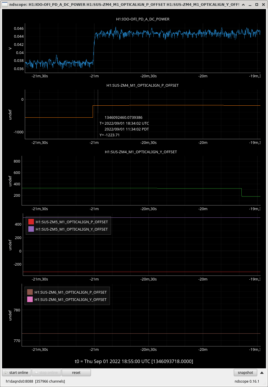
This is great Robert! To confirm that no horizontal move of OFI_PD_A is needed, I found a time from alog64811 when we had power up to our ~max 44uW by adjusting ZM4 pitch and leaving yaw at IFO aligned position... now to find a 2mm spacer..