- Grounding check for ISC. Problem found and fixed.
- Used the viewport simulator on +X door to see if the beams (ASAIR and OMC TRANS) will come out of the viewports. They'll be fine.
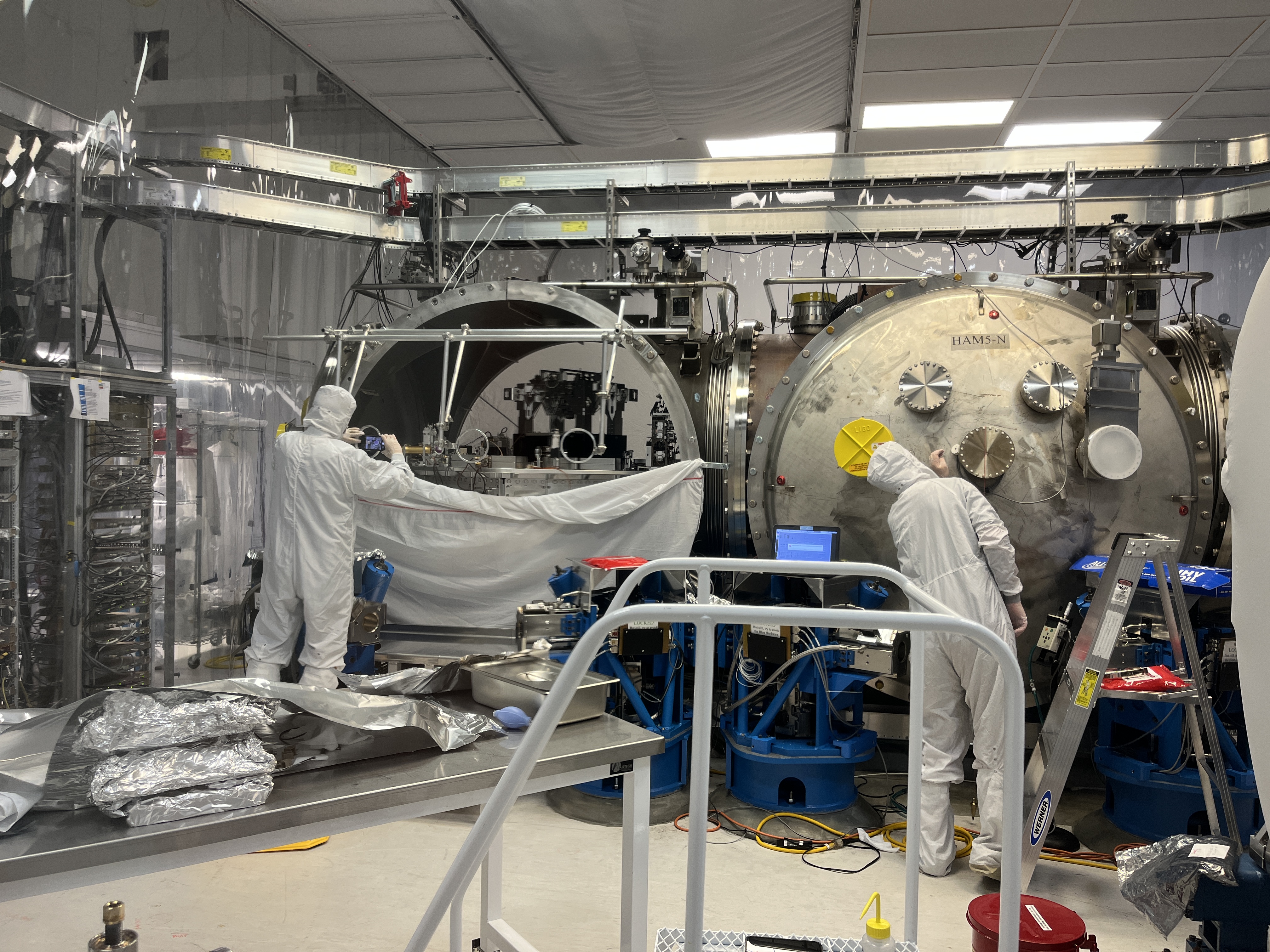
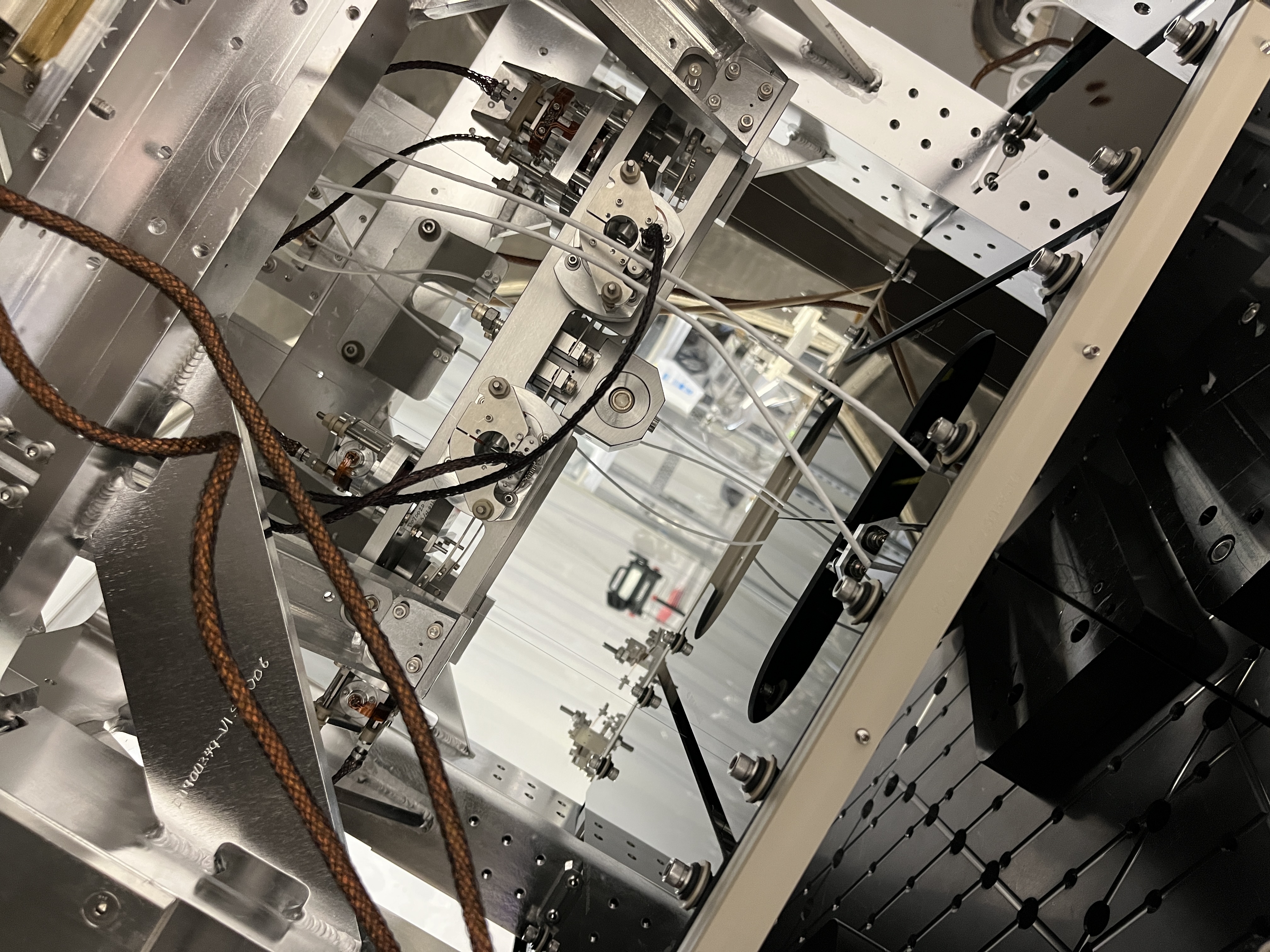
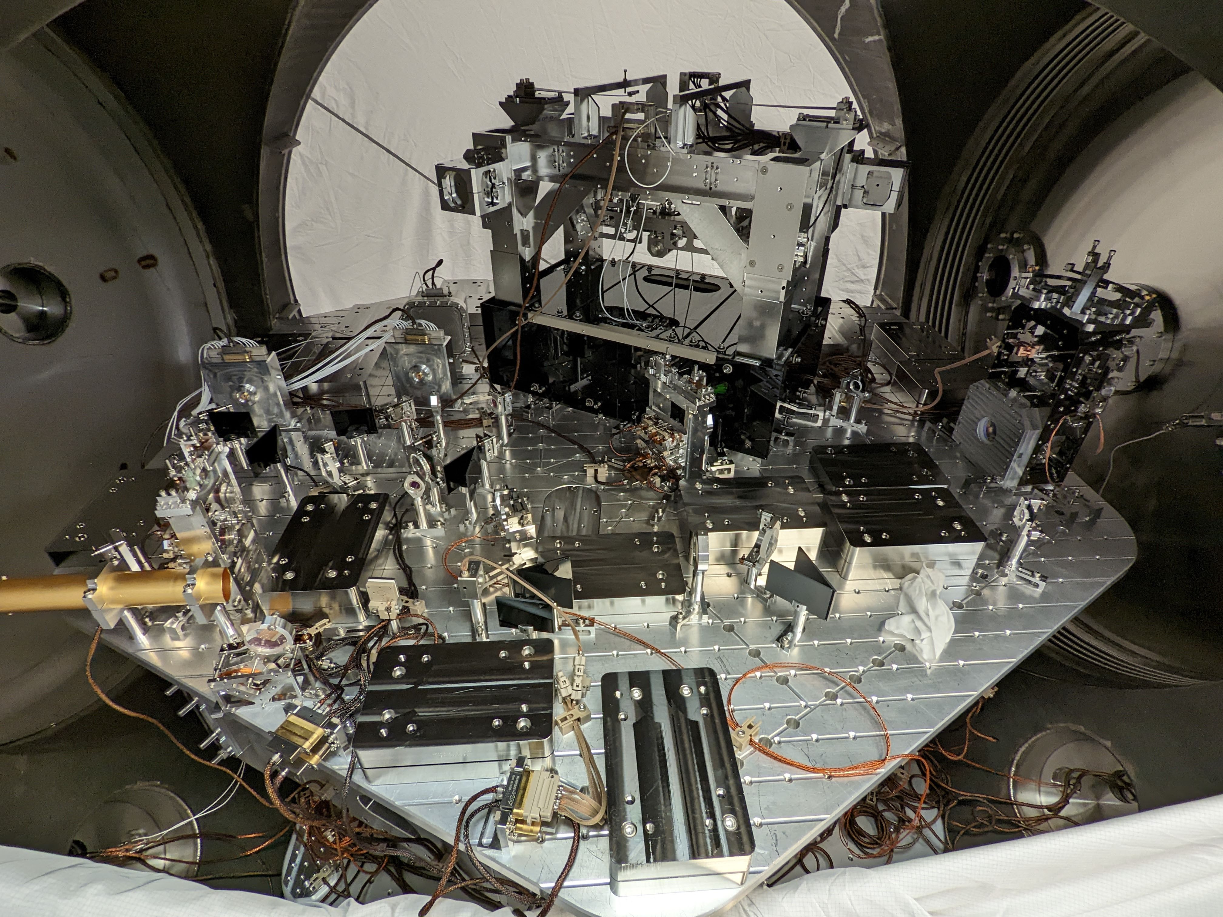
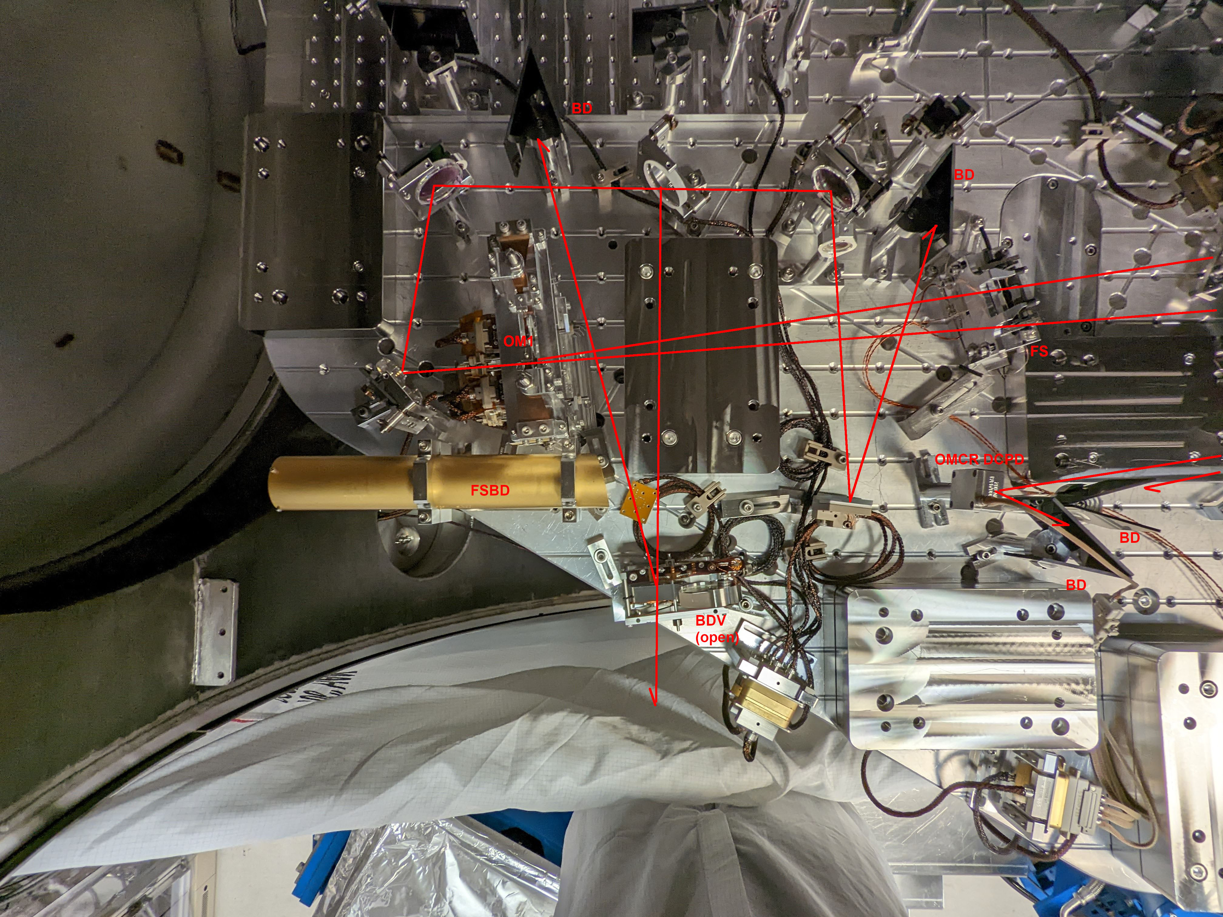
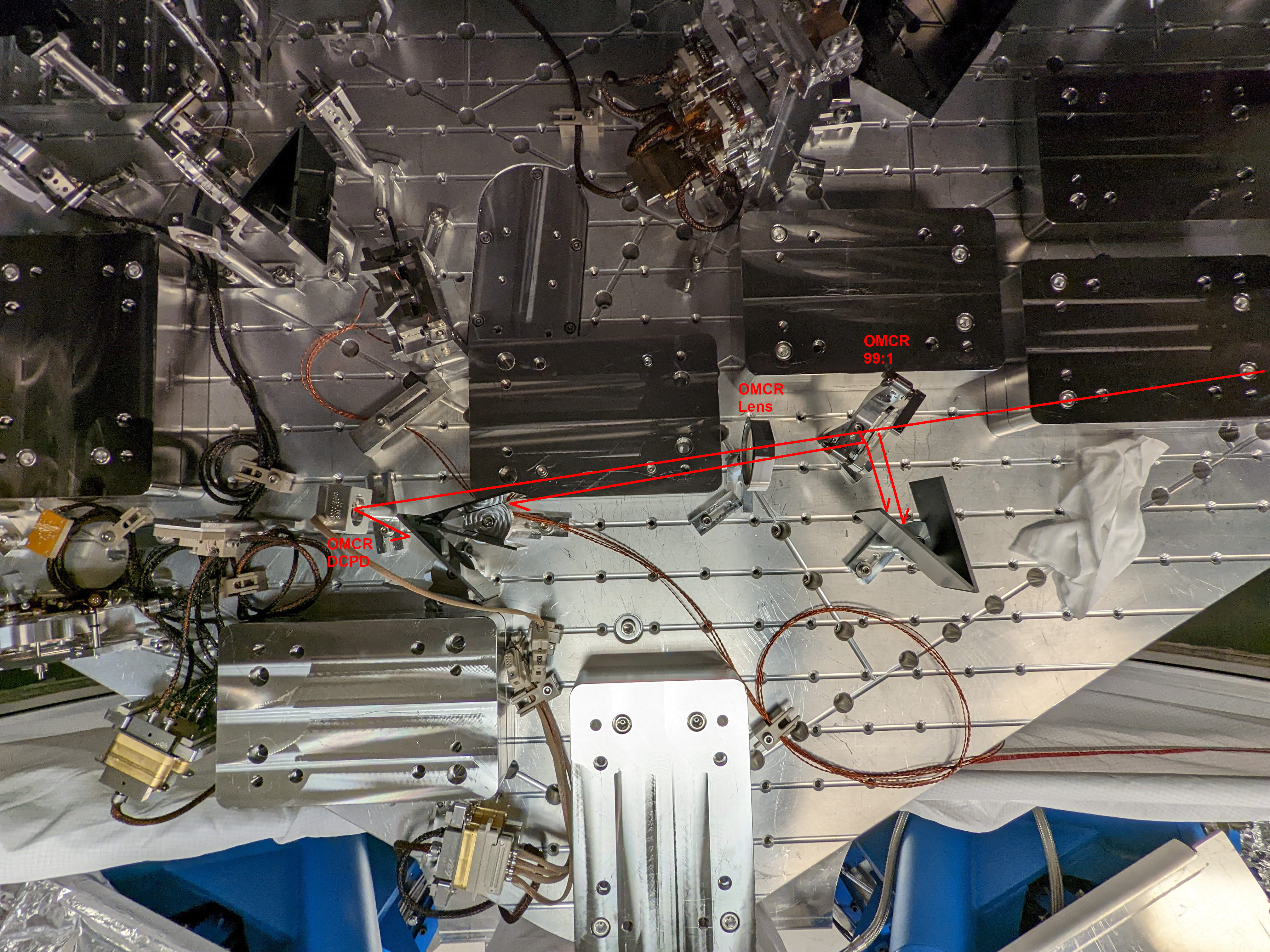
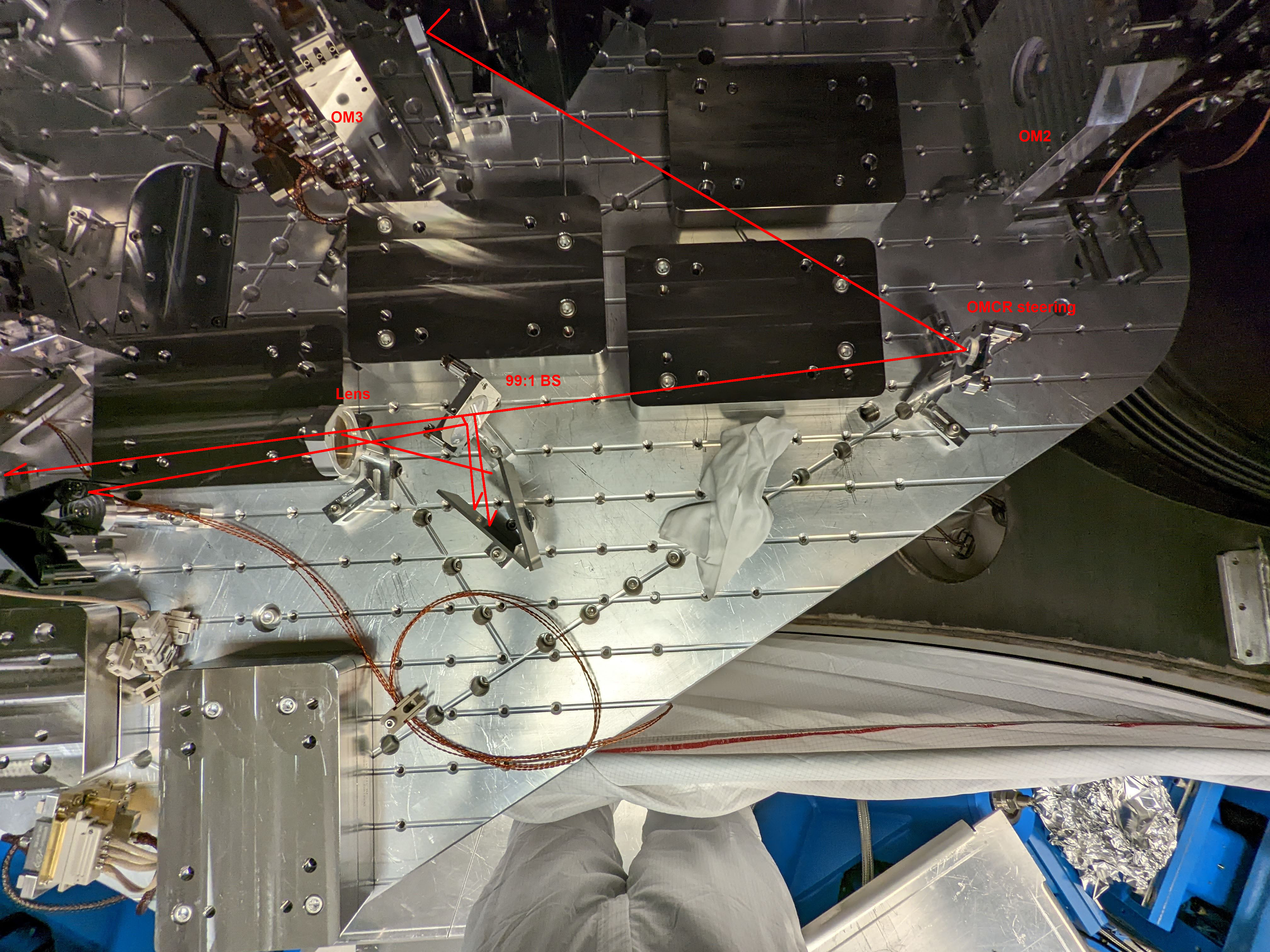
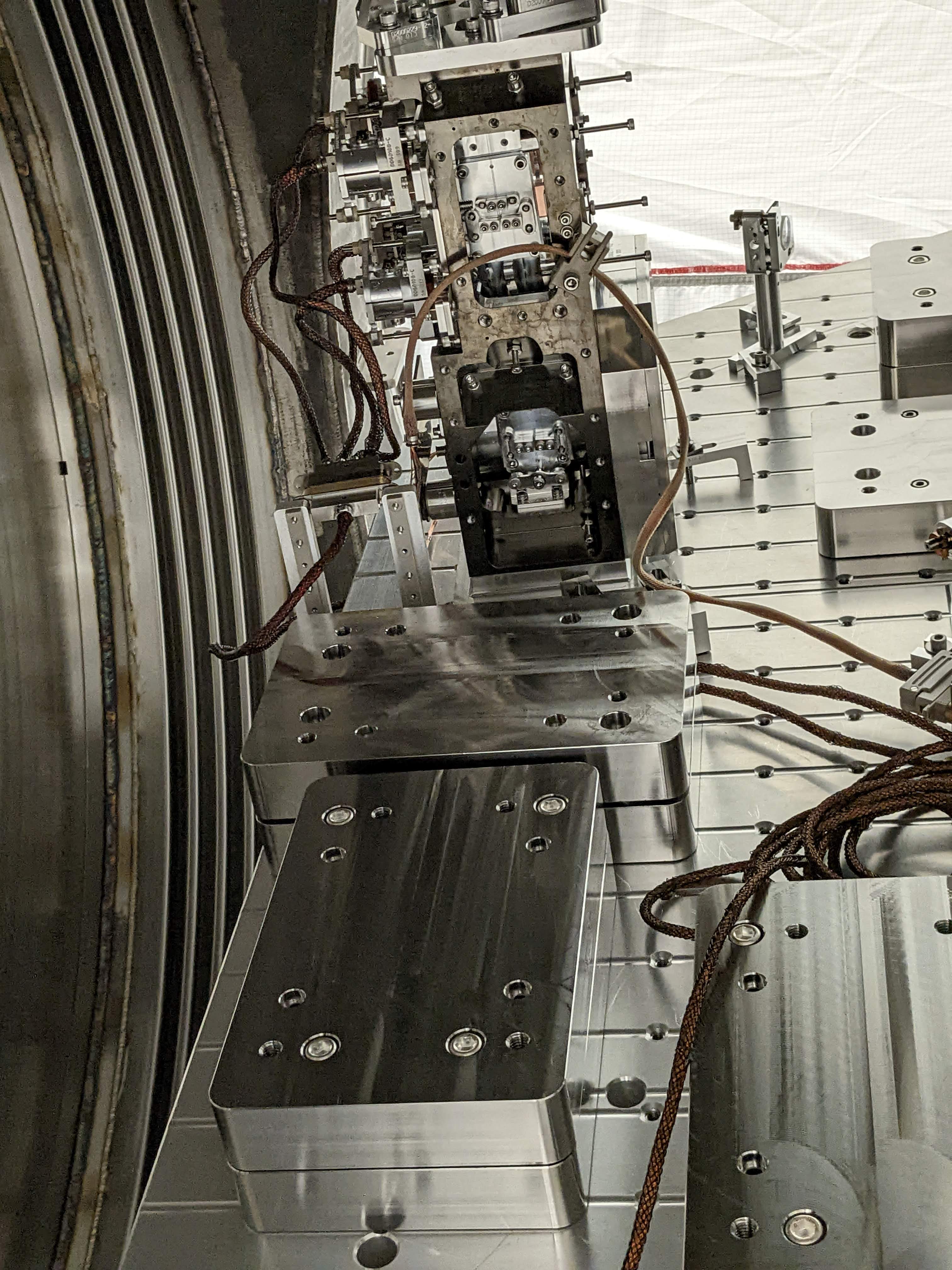
- Took pictures of the table layout.
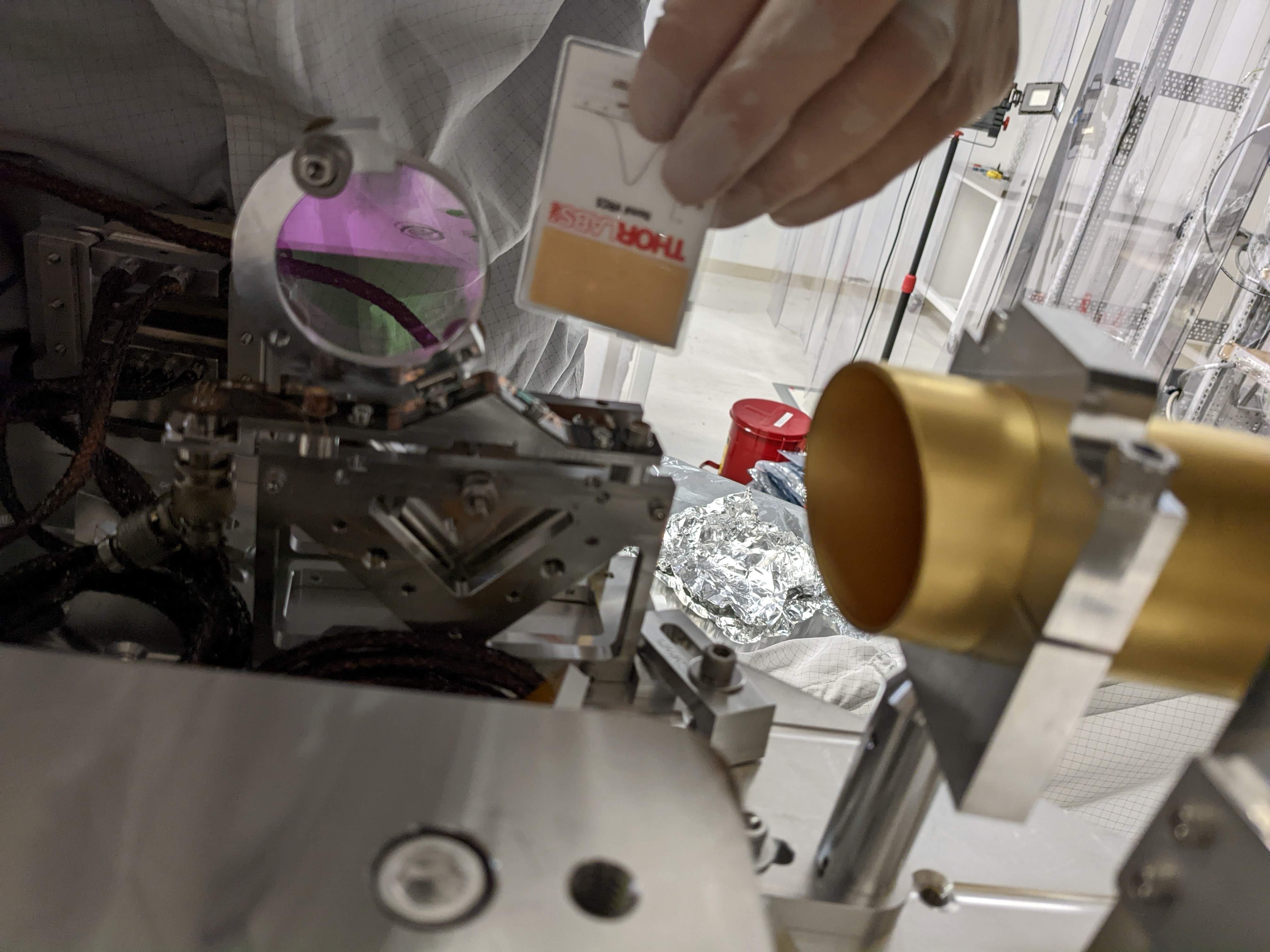
- Jim put an wafer on the table.
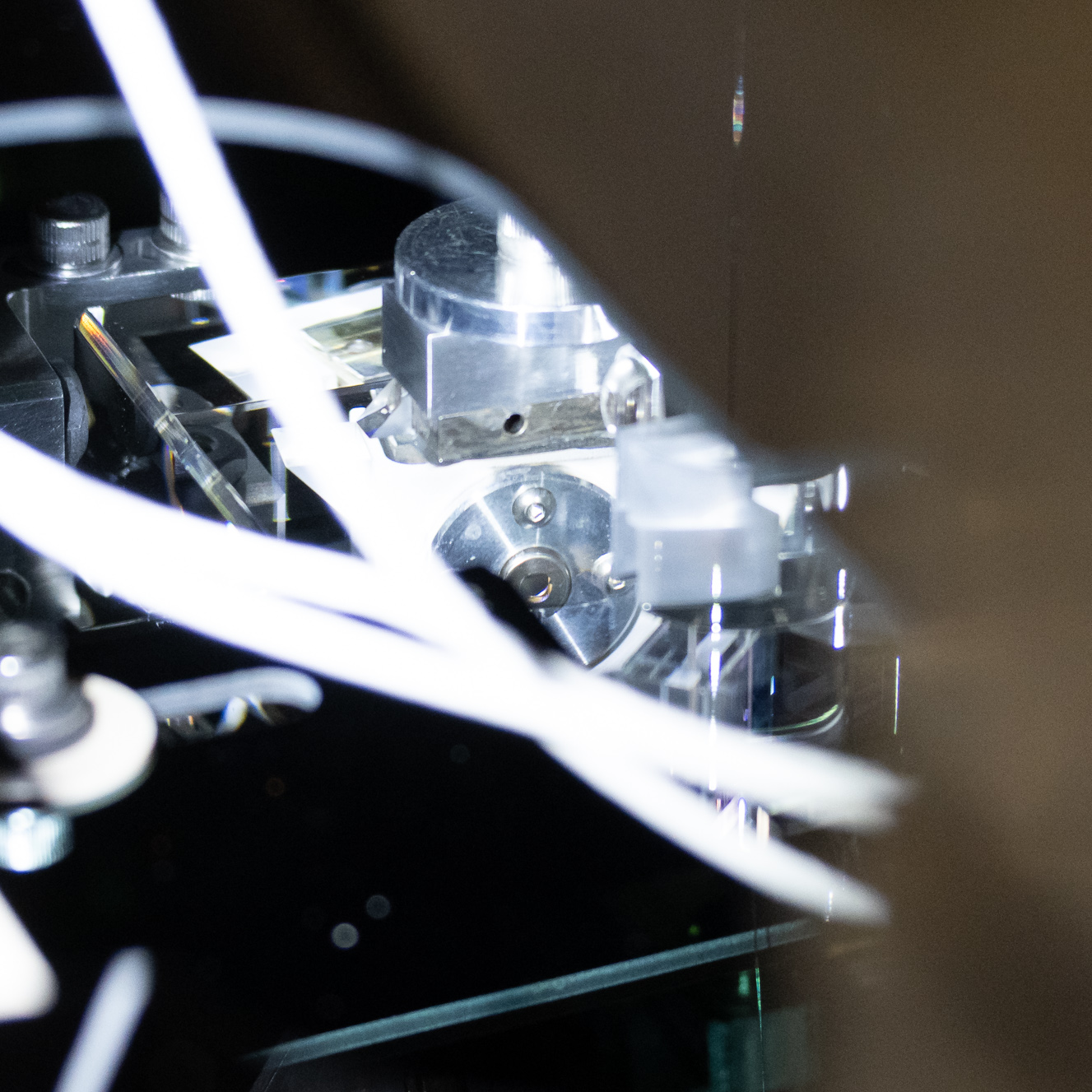
- I tried to take good picture of the OMC DCPD surface, but it's impossible without removing the OMC shroud, so we gave up.
- Rahul took SUS TFs and they're fine.
- HAM5 gatevalve was closed, foil removed, and the plastic cover was put on.
- Jim unlocked ISI.
- Cleanup work by everybody.
- HAM6 ready for the door.
Some details.
Grounding.
I and Jim checked the ground loop for everything on A6 flange (ISC) again. I disconnected in-air cables from the feedthrough, put a DB25 breakout board on the feedthrough and tested the connection between pin13 (in-chamber shield) and the chamber ground.
The only genuine problem we found and fixed was a ground loop for ASC-AS_C QPD cable. Jim rerouted that cable that was bunched up under the ISI and it was fixed.
Also, when testing ground check for F1(OMC DCPD)/F2(OMC PZT)/F3(OMC QPD), disconnecting these three isn't enough. Don't forget to disconnect 3MHz cables (D4-2B1 and D4-2B2), otherwise there's this path which gives you anything from a few hundred kOhm to 4MOhm. We wasted some time because of this.
F1 in-chamber shield <-> DCPD preamp signal ground <-> RF cable SMA shield <-> SMA Rack ground -> chamber ground.
After disconnecting RF cables, don't forget to torque them using a dedicated torque wrench for SMA.
As of now, in-air cables on D6 are as follows.
|
D6 feedthrough number |
In-air Cable | Description |
| F1 | ISC-307 | OMC DCPD |
| F2 | ISC-409 | OMC PZT HV |
| F3 | ISC-404 | OMC QPDs |
| F4 | ISC-232 | OMCR DCPD |
| F5 | ISC-233 | ASC-AS_C QPD |
| F6 |
None |
Used to be OMCR pico, old ISC-235 cable was removed. No cable in chamber either. |
| F7 | ISC-234 | AS_C pico |
| F8 | ISC-317 | ASAIR Beam Diverter |
| F9 | T-SAMS | OM2 heater |
| F10 | ISC-236 | OM1 BOSEM |
| F11 | ISC-237 | OM2 BOSEM |
| F12 | ISC-238 | OM3 BOSEM |
AS_AIR beam position check
TJ and Tony installed viewport simulator on the +X door after adjusting the hoop positions on the real door.
From the picture I previously took (ASAIR_beampos.jpg), I know that the ASAIR beam position is about the radius of the BDV optic toward -Y direction at the BDV when it's open.
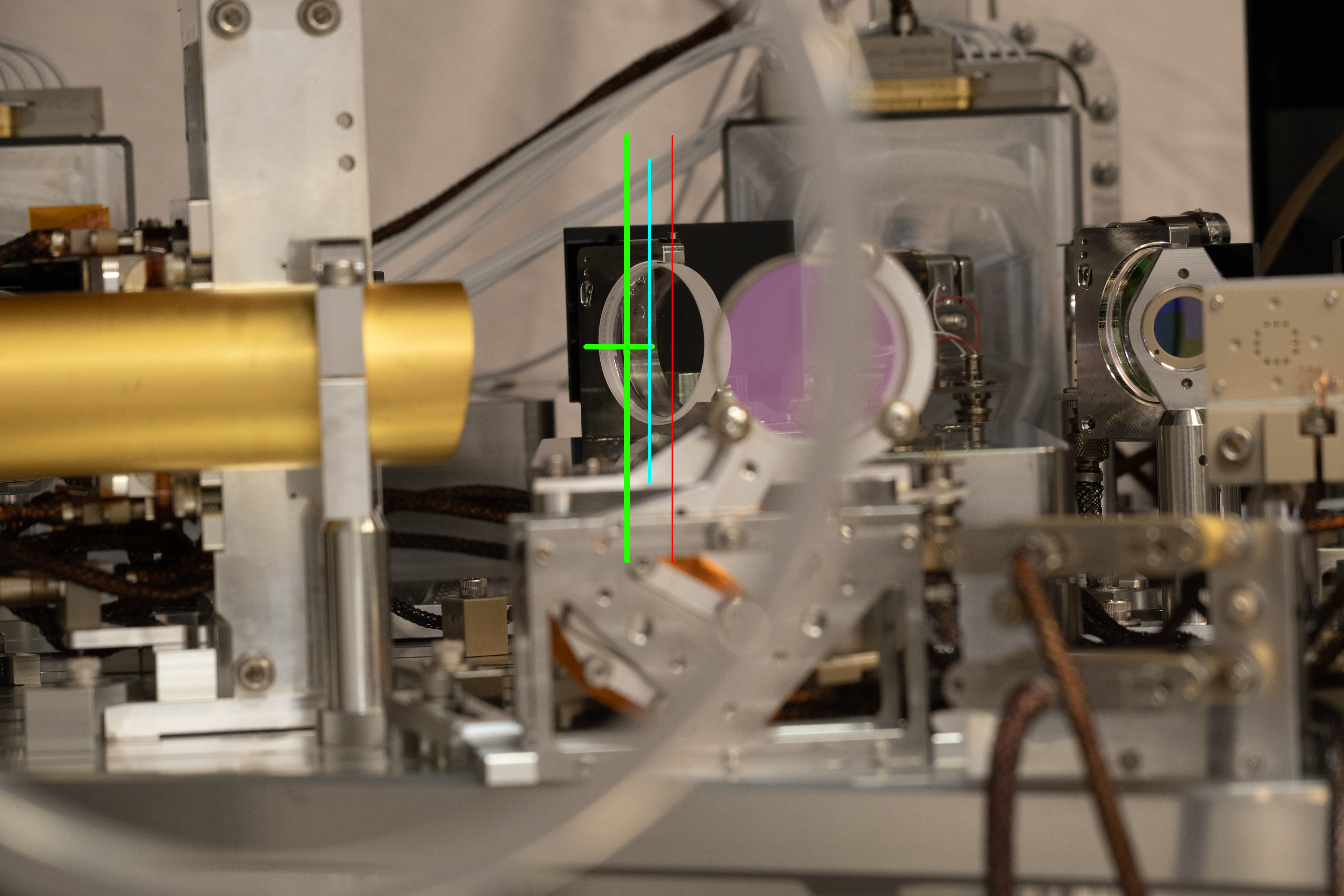
So I placed the camera so that the lens is co-axial with the line connecting the center of the ASAIR beam position by the BDV and the center of the ASAIR-AS_C splitter as good as I can (ASAIR_likely.jpg). Green cross is where I think the beam will be by BDV. Cyan line is the center line for ASAIR-AS_C BS. (Red line is the center line of the lens just so you know how big the parallax could be.)
Anyway, as far as the centering on the BS is not terrible, the beam will come out w/o any problem.
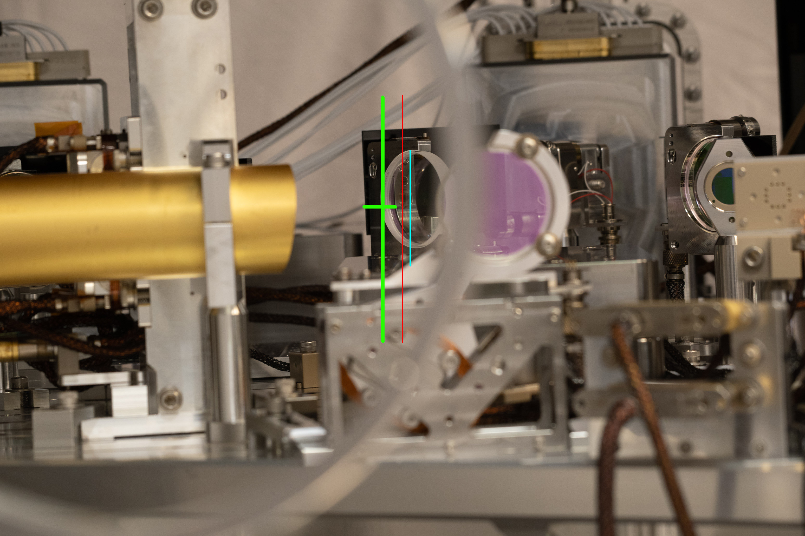
I also repositioned the camera to assess the worst case scenario (the beam will be very close to the left edge of the BS and therefore comes closest to the right edge of the viewport given the fixed position of the ASAIR beam by the BDV), and the beam will still come out of the viewport.
OMC TRANS beam check
We haven't done anything as there's no reason for a big change except that we changed how OMC ISC cables are routed inside OMCS, and that we removed OMCS suspension offsets. Just took one picture through the +Y hoop of the viewport simulator.
Table layout pictures
For posterity.
Couldn't take a good DCPD picture
I tried to take a good picture of at least one of the OMC DCPDs through the space between OMC shroud panels and through the OMC breadboard itself but I couldn't. The view is there but lighting is not (DCPD.jpg).

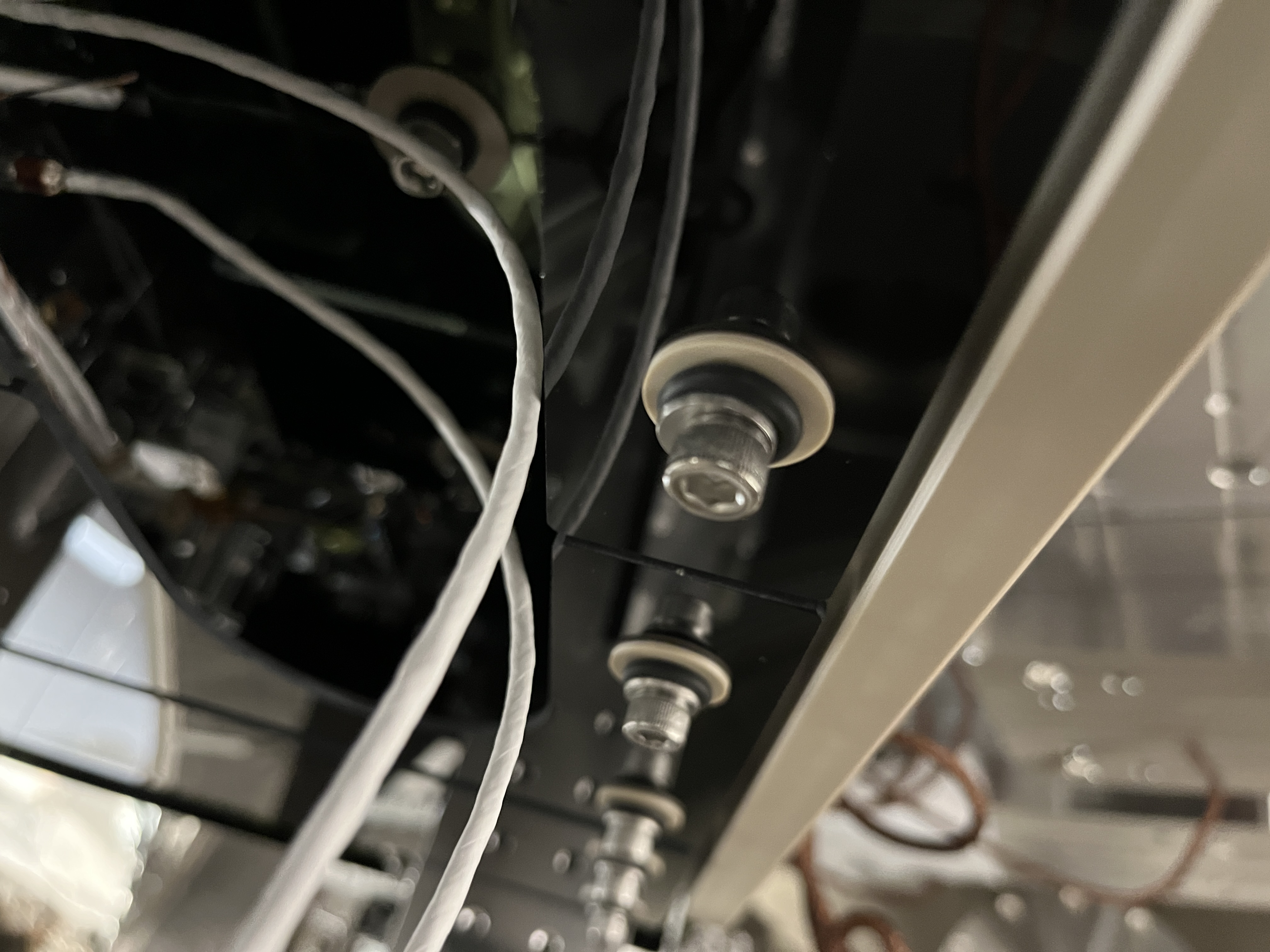
A couple more pics from my phone, late to alog.
Not the OMC pictures are of the suspended cables touching the glass baffle BEFORE we corrected it to not touch.