jeffrey.kissel@LIGO.ORG - posted 14:18, Wednesday 12 October 2022 - last comment - 15:07, Wednesday 12 October 2022(65310)
H1SUSSRM and H1SUSSR2 M1 DAMP Filters Re-Arranged; Level 2 Design Characterized and Ready to Use
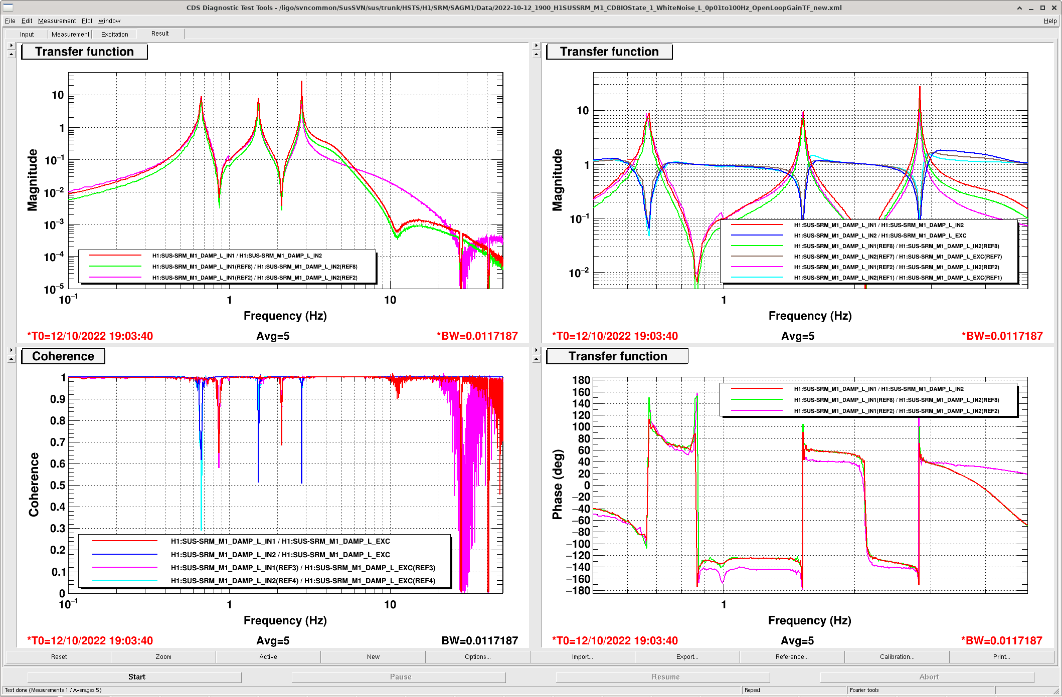
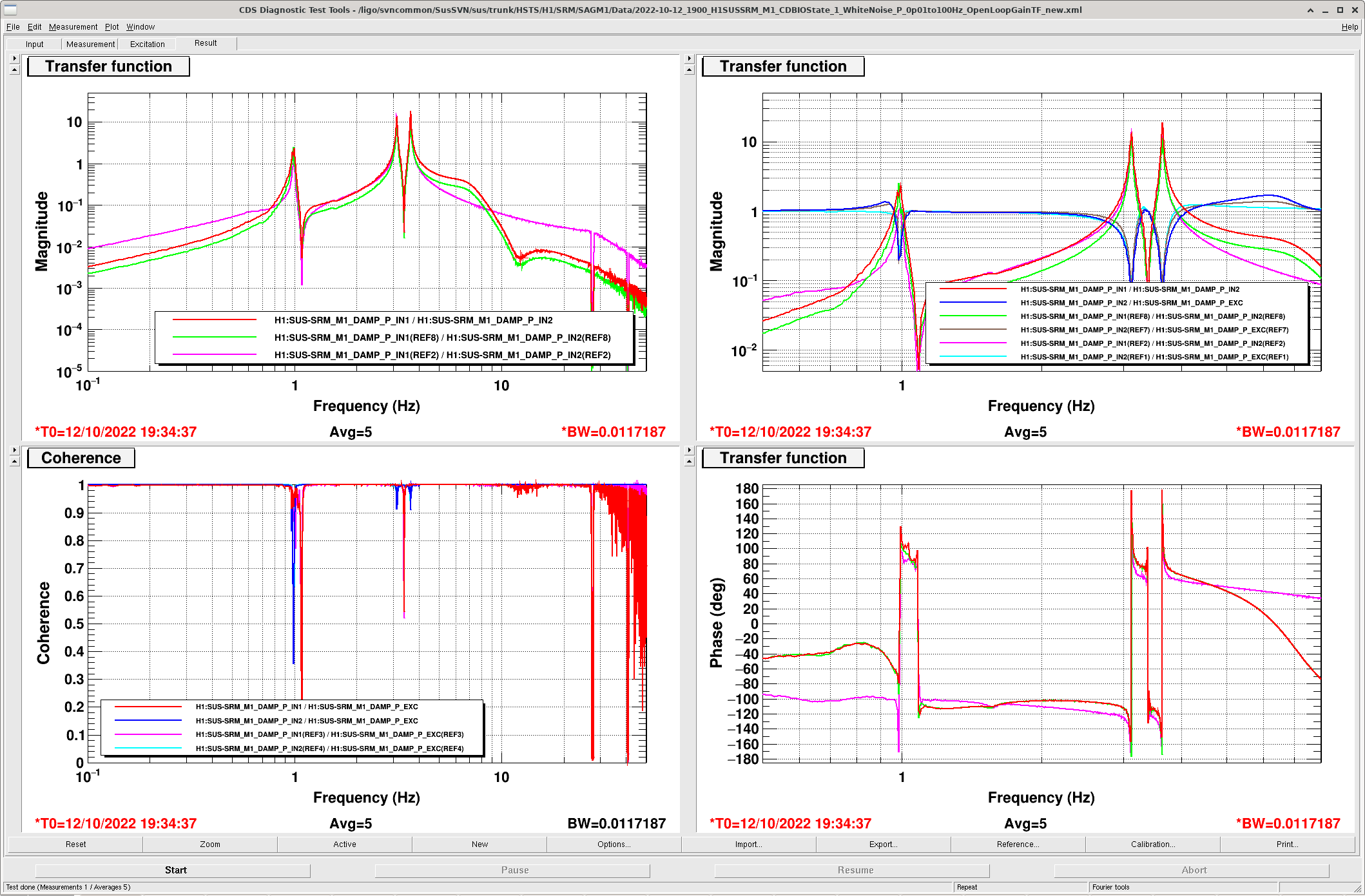
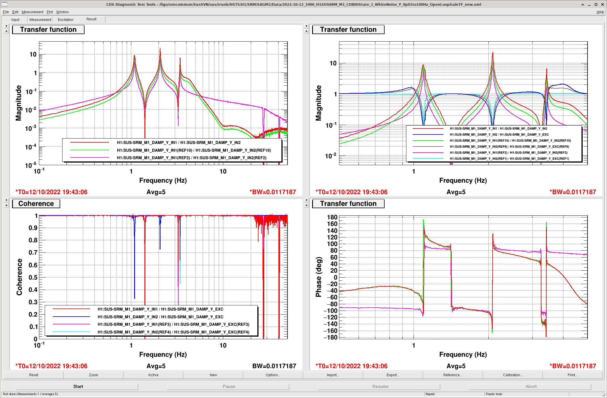
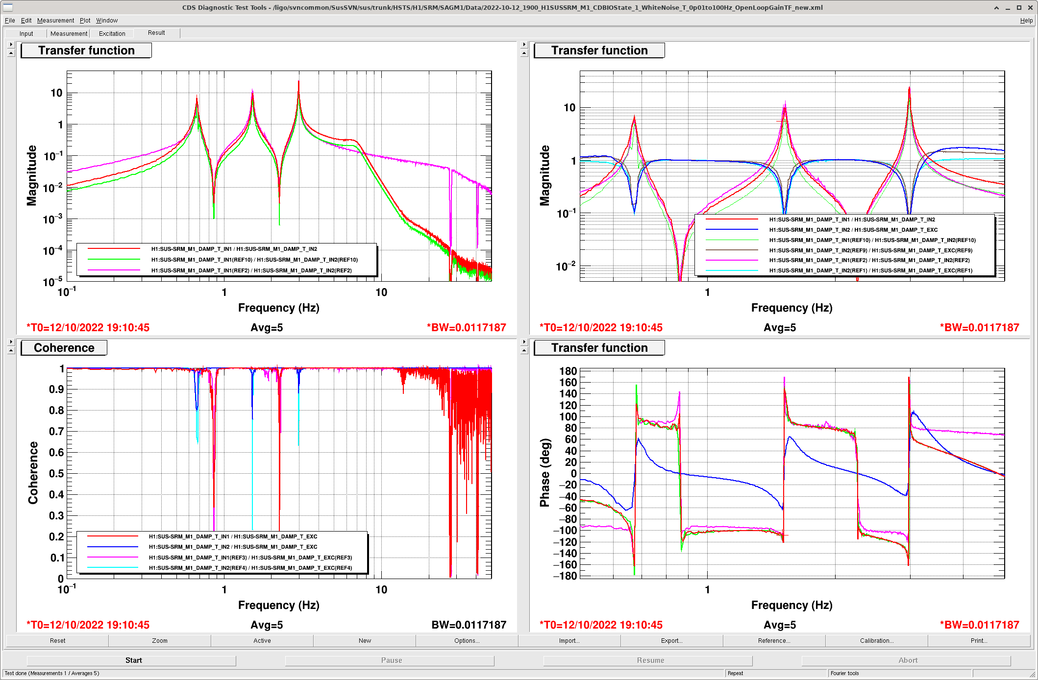
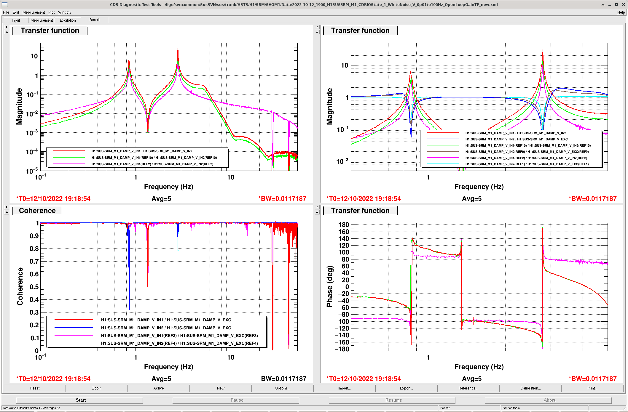
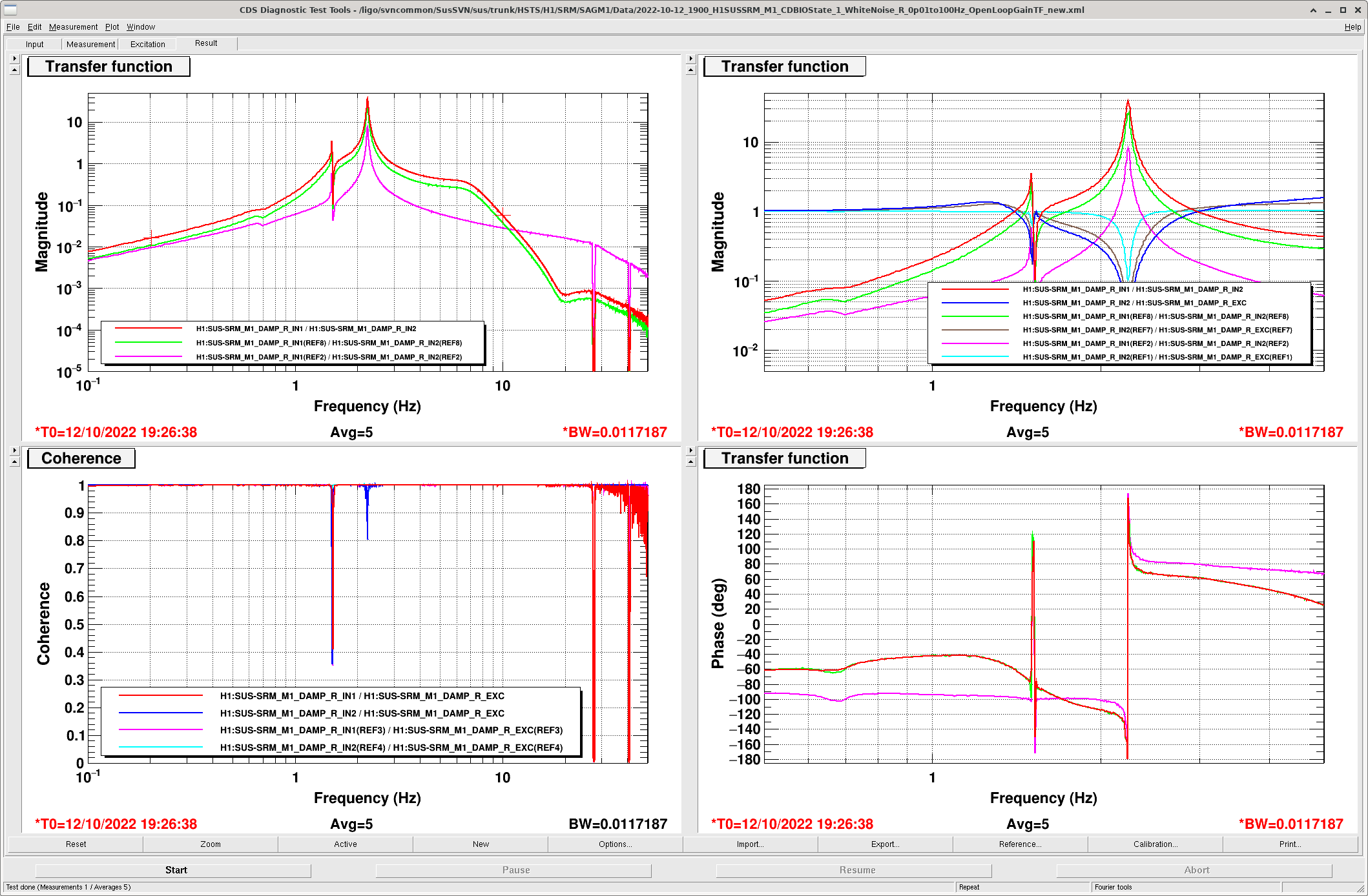
E. Capote, J. Kissel

In anticipation of their future desired use, Elenna and I installed the improved HSTS damping filters into the M1 DAMP filter banks of H1 SUS SRM and H1 SUS SR2. The filters are the same discussed in LHO:65257, used in recent budgets of DAC noise studies (see LHO:65247) -- which are only slightly augmented from the "Level 2" designs of old from G1401290 (see where / how they're different in LHO:65257). As a part of the now-standard practice of install, we also took the time to characterize the open loop gain transfer functions, as shown in the attached screenshots below. Doing so allows scaling of the open loop gain to better match the model, such that we get the modeled noise performance, damping ring-down times, modified "global control" transfer functions to the optic, etc. I mentioned briefly in LHO:65247 that I was much more confident in my model's calibration, and indeed this was the case here -- we needed only to scale the "as-designed" filters by an overall gain of 1.5x to match the modeled open loop gain.

To avoid plot-overload, in this main aLOG I attach only the L, P, and Y open loop gain TF comparisons for SRM. For each DOF, I show a quad-panel plot with the following content:
    :: Upper Left: broad, full-frequency range, magnitudes of the open loop gain transfer functions.
        - In RED is the "final answer" OLGTF, with the filters scaled with a gain of 1.5 from the design values.
        - In GREEN is the intermediate answer, where we show the OLGTF with the "as designed" gain scale.
        - In MAGENTA is the OLGTF of the old filter design.
    :: Lower Left: the coherence between the Excitation and each IN1 and IN2 test point, just to prove to you that it's really good,
       and we can trust all phase information from the OLGTF as we whip around the unit circle quickly around all the high Q features.
    :: Upper Right: A zoom in on the OLGTFs with the same color scheme as Upper Left, but also showing the loop suppression (1/1+G), to convey
       the amount of gain peaking in
        - the scaled new (in BLUE),
        - the as-designed new (in BROWN), and
        - the old (in CYAN)
       filters. One can see that no gain peaking is larger than a factor of 2.
    :: Lower Right: the zoomed in phase of the OLGTFs, with the same color scheme as the other panels.

These filters create:
    - Equal or greater on-resonance open loop gain / suppression / Q-reduction
    - Sacrifice noise by yielding more re-injection by increasing gain between the highest resonance and ~5 Hz by only factors of 2-5, but
    - Improve noise rejection by factors of 10x to 50x with improved roll-off / cut-off / elliptic filters above 5 Hz.
    - Reduce the unnecessary DAC drive-request above ~5 Hz.

The hope is that they *do not* impact the global control transfer functions too drastically, and SRC ISC loops do not need a heavy amount of re-work, but this remains to be seen.
There is sufficient amount of evidence out there that the BOSEM sensor noise was dominating the SRC ISC loop noise between ~5 Hz and ~30 Hz (see e.g. LLO:55074, G2100193, LHO:64093), so these filters should help a great deal.

However, in order to compare the noise improvement and changing in global control plants, we've moved the former filters (the "LHO Current" from G1401291) into FMs 6-9 such that they can still be used. In fact, we've left the SUS using the old "LHO current" damping filters such that there's less that has changed over the vent so recovery may be less confusing. The plan will thus be to engage these filters after recovery, so we can do a nice "old vs new" comparison of the ISC loops. As I'd done with other suspensions, however, we moved any EPICs gain into an "old_gain" filter module that includes the former "norm_${DOF}" as well. As such, all EPICs gains for all DOFs are now -1, to make it easy to flip back and forth between configurations.

Lots more details in the comments below.
Images attached to this report
Comments related to this report
Here're the OLGTFs for the other DOFs of SRM -- T, V, and R.
Images attached to this comment
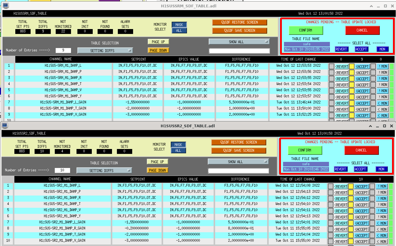
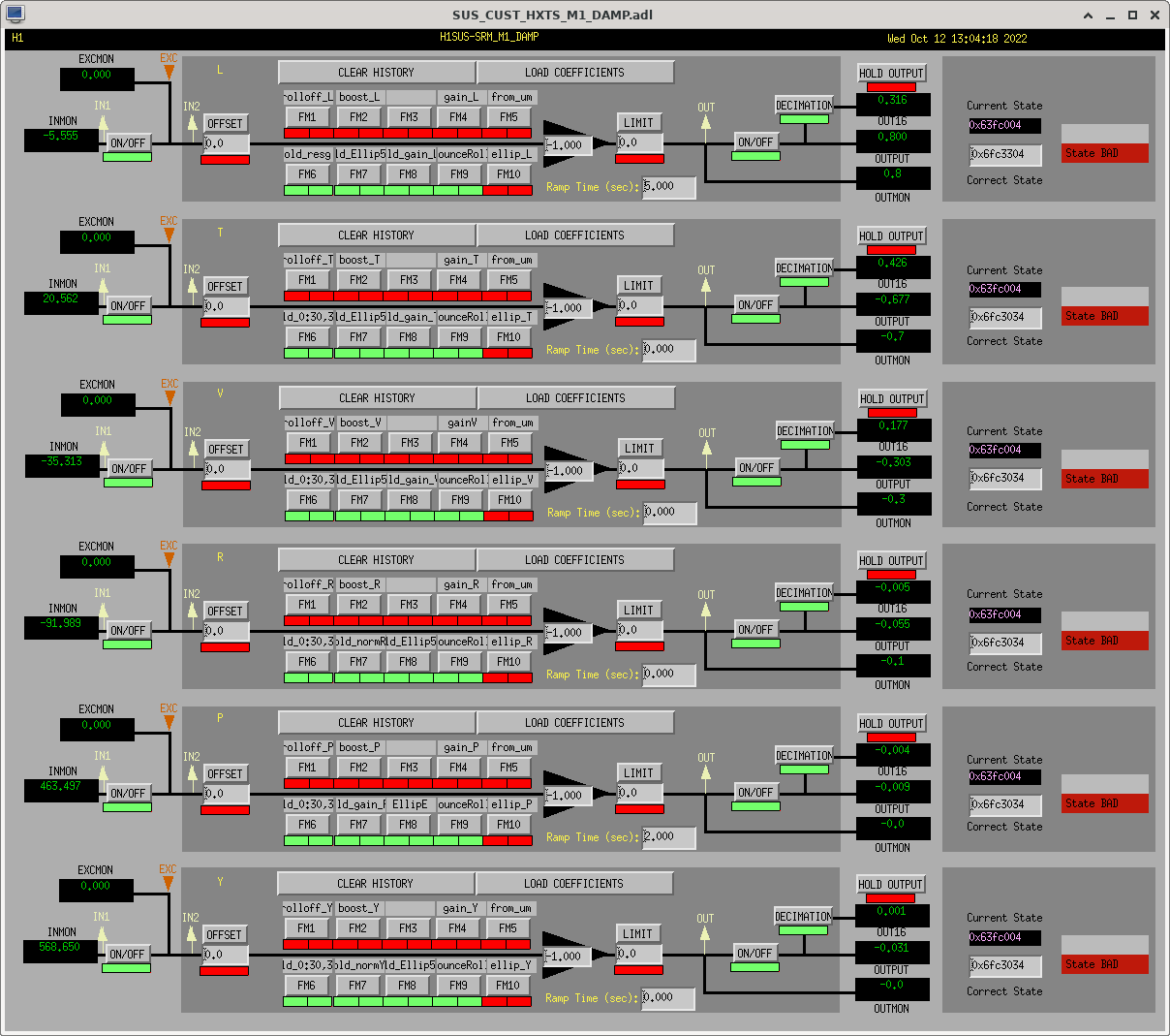
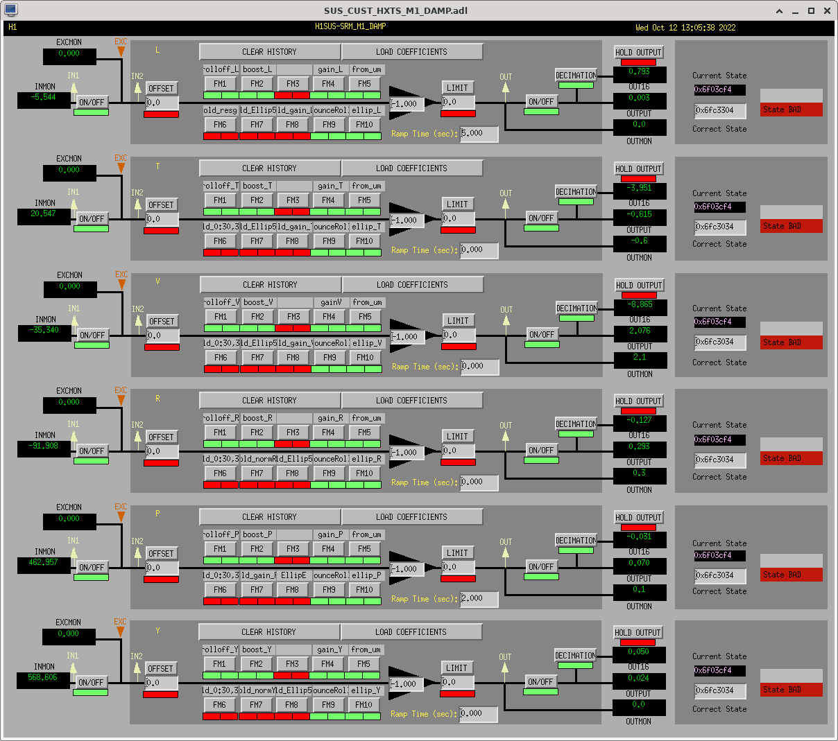
The old filters, in their new locations, as well as the EPICs gains of -1.0 have been saved into SRM and SR2's SDF system. See the following attachments:
   - 2022-10-12_H1SUSHSTS_SRMSR2_M1_DAMP_FilterRearrangment_SDFAccept.png screenshot of the SDF values accepted into the safe.snap,
   - 2022-10-12_H1SUSSRM_M1_DAMP_FilterRearrangment_OldConfig.png screenshot of the DAMP filter bank while in the "old" LHO Current filter configuration.
   - 2022-10-12_H1SUSSRM_M1_DAMP_FilterRearrangment_NewConfig.png screenshot of the DAMP filter bank while in the "new" Level 2 filter configuration.
Images attached to this comment
Regarding the scale factor of 1.5 between as-designed value and measured value of the Open Loop Gain TF

When we measured the open loop gain transfer functions of the freshly installed, as-designed filters, the results had less gain than predicted by the model. This is not unexpected, as the model relies on a generic calibration of the sensing and actuation chain which can easily result in an overall scale factor discrepancy from suspension to suspension. In addition, the dynamical model's predicted resonance frequencies, stiffness, and masses / moments of inertia might be slightly different from reality in general, as each suspension might be slightly different on top of that as well.

As such, we exported the GREEN open loop gain TF traces above and compared them against the model directly. One can see this model comparison against the measured results for SRM and SR2 in the attached .pdf, dampingfilters_HSTS_OLGTF_model2022-10-05_vs_meas2022-10-11.pdf.

The first six pages are for the six DOFs, showing the magnitude, phase, and magnitude ratio between model and measurement.
For the reasons described above, and thus, as expected, the magnitude ratio is frequency dependent, not consistent between degrees of freedom, and not consistent between SRM and SR2.

BUT
   - all the magnitude ratios are between 1.1 and 1.9
   - the low-frequency and high frequency asymptotes are typically within 0.1 of each other, and
   - the difference between 1.1 and 1.5 (i.e. a ~30% different) doesn't matter in terms of Q-reduction and noise re-injection.
So, in the interest of keeping the design maintenance simple (in our, humble opinion, far more preferable than "better than ~30% consistency in noise performance and Q reduction / ring-down time."), we took an eye-ball average of it all, and applied a consistent, frequency dependent factor of 1.5 to all DOFs.
Non-image files attached to this comment

The templates for measuring the open loop gain transfer functions for the old vs. new filters can be found in the following location.
One MUST have the top drivers in the high-range configuration, State 1, with the ACQUIRE filter ON, or rather the low-pass filter OFF.

/ligo/svncommon/SusSVN/sus/trunk/HSTS/H1/SRM/SAGM1/Data/
    2022-10-11_2122_H1SUSSRM_M1_CDBIOState_1_WhiteNoise_${DOF}_0p01to100Hz_OpenLoopGainTF_old.xml   # Old Filter Design
    2022-10-11_2252_H1SUSSRM_M1_CDBIOState_1_WhiteNoise_${DOF}_0p01to100Hz_OpenLoopGainTF_new.xml   # New Filter Design, as-designed gain scale
    2022-10-12_1900_H1SUSSRM_M1_CDBIOState_1_WhiteNoise_${DOF}_0p01to100Hz_OpenLoopGainTF_new.xml   # New Filter Design, scaled by 1.5x

/ligo/svncommon/SusSVN/sus/trunk/HSTS/H1/SR2/SAGM1/Data/
   2022-10-11_2100_H1SUSSR2_M1_CDBIOState_1_WhiteNoise_${DOF}_0p01to100Hz_OpenLoopGainTF_old.xml   # Old Filter Design
   2022-10-11_2300_H1SUSSR2_M1_CDBIOState_1_WhiteNoise_${DOF}_0p01to100Hz_OpenLoopGainTF_new.xml   # New Filter Design, as-designed gain scale
   2022-10-12_1900_H1SUSSR2_M1_CDBIOState_1_WhiteNoise_${DOF}_0p01to100Hz_OpenLoopGainTF_new.xml   # New Filter Design, scaled by 1.5x

Note that we were *mostly* able to use the same drive excitation levels for both SRM and SR2, but because SRM has much larger alignment offsets than SR2, I needed to back off a bit for pitch and yaw.
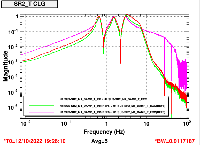
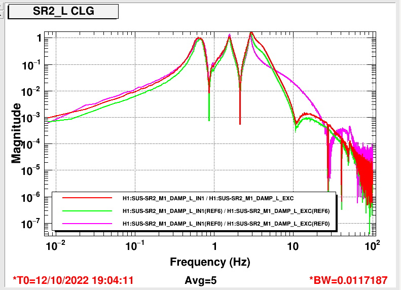
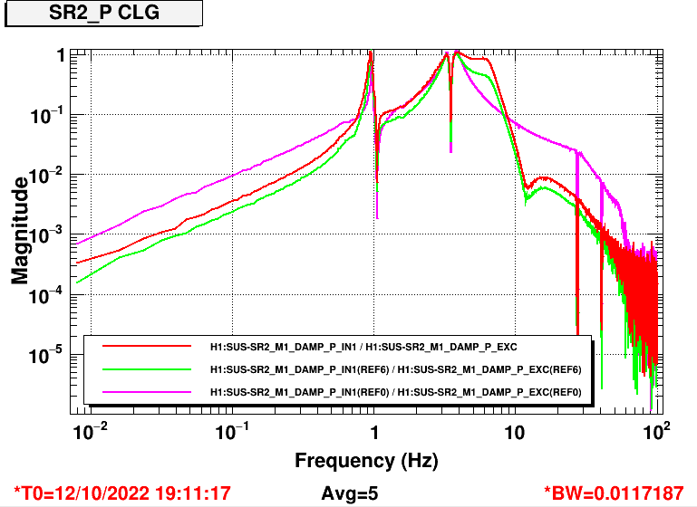
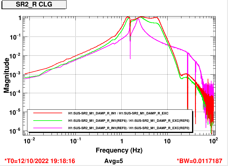
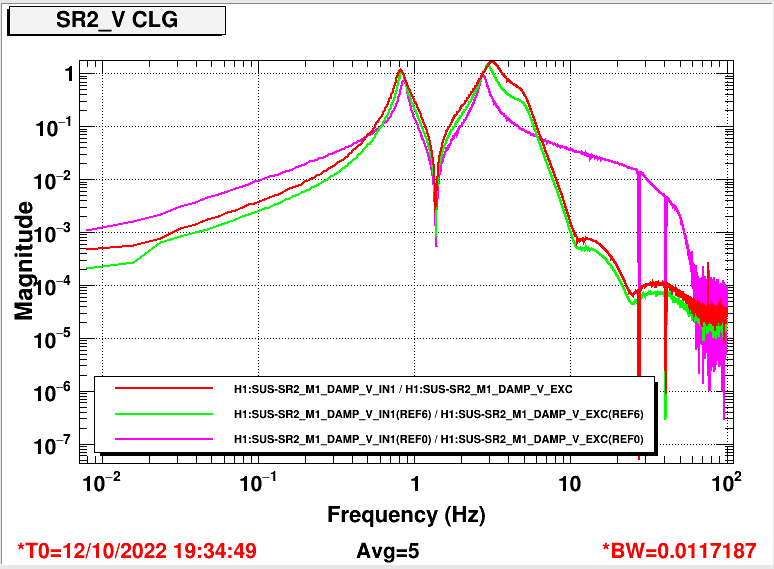
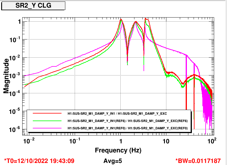
Adding the closed loop gain plots of all dofs. These are from SR2, but the SRM and SR2 measurements are very nearly identical.
Images attached to this comment