Daniel, Vicky, Dhruva, Nutsinee
Although the filter cavity was locked last Friday, the error signal didn't actually look that grandeous. So, we went to investigate -- first by making sure the modulation index was reasonable.
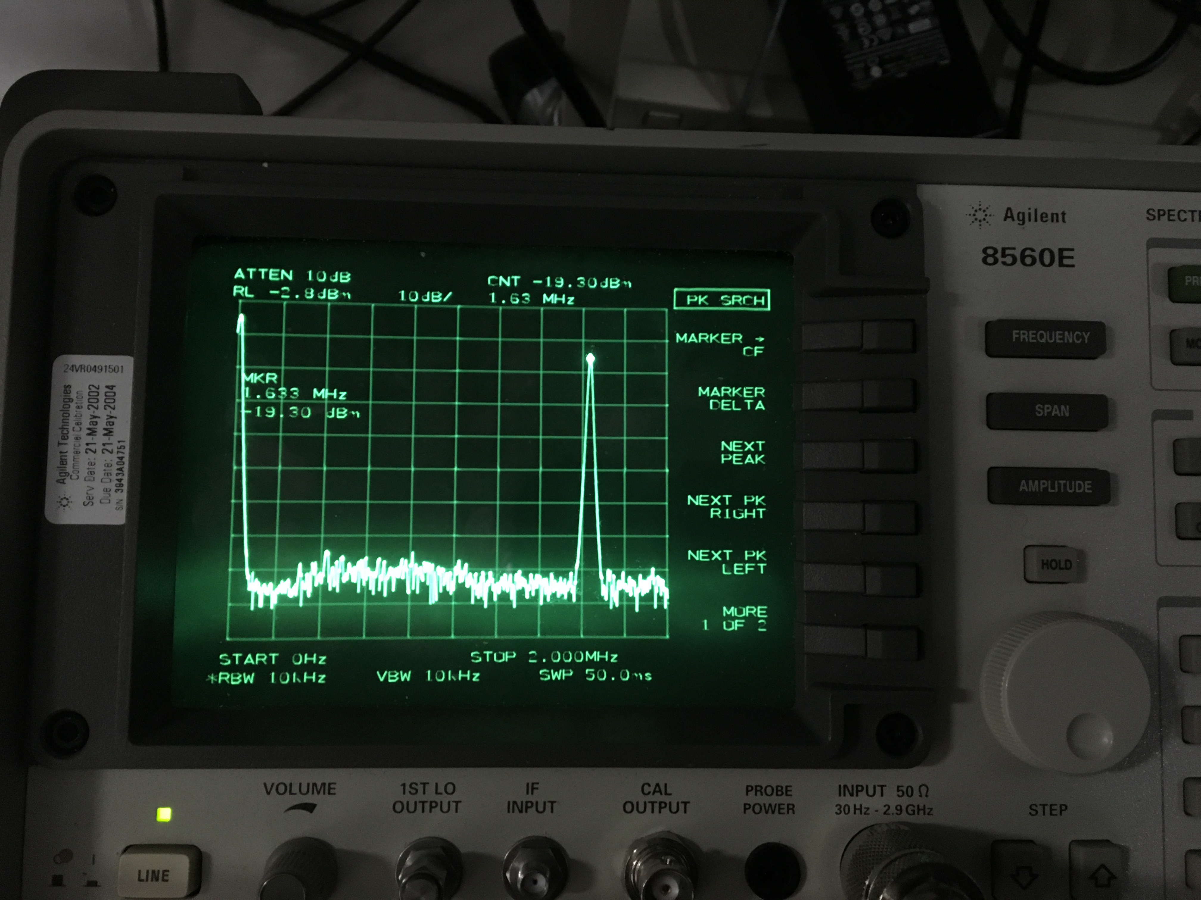
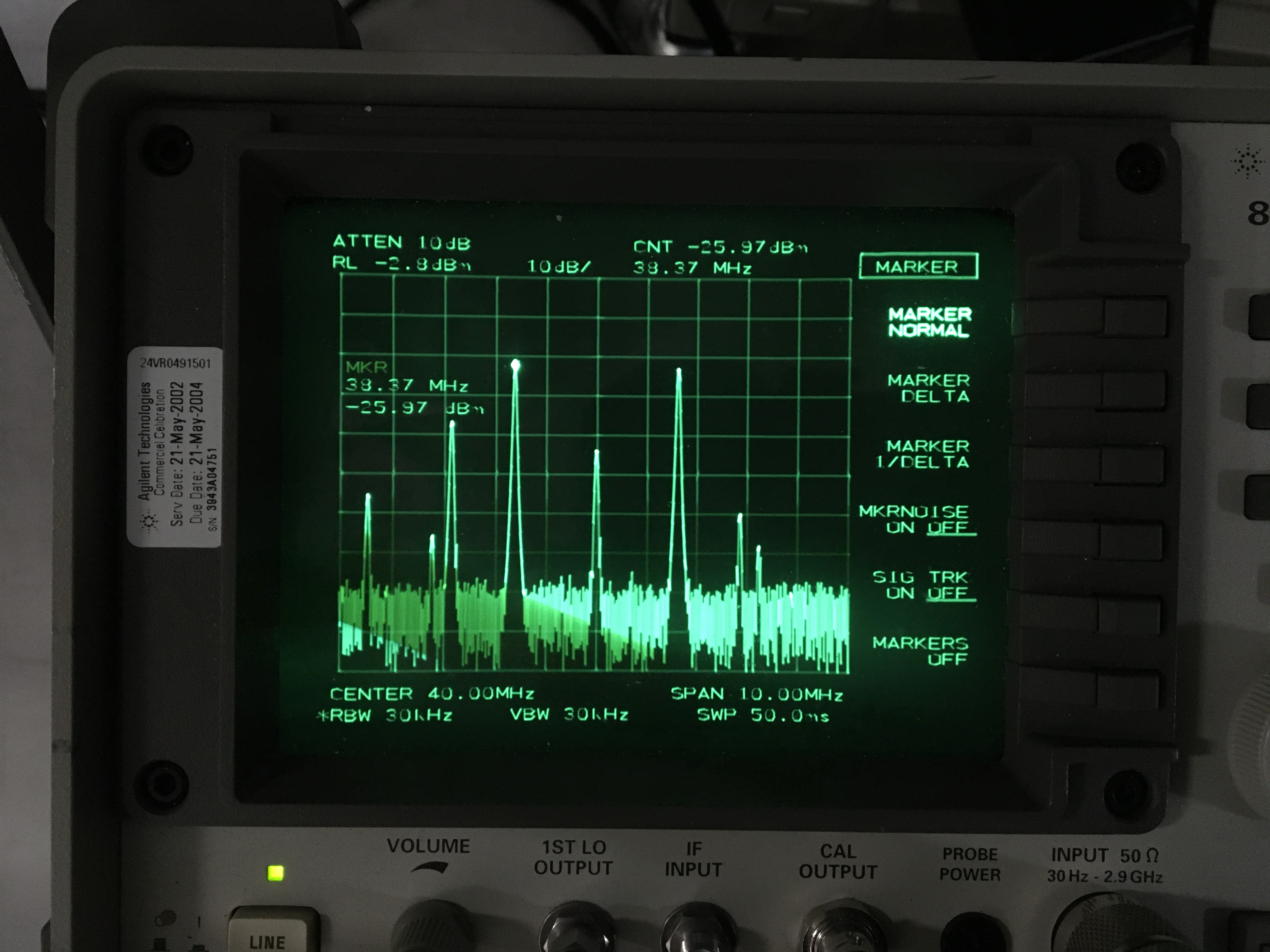
To figure out the modulation index of the FC 40MHz signal we looked at the beat note on the SK path. We replaced the Thorlabs diode with a broadband PD (spare OPO refl diode) so we can see 40 MHz. Next we shifted the FC green beam to 1.6MHz away from the carrier (OPO refl). We measured -19.3 dBm on the 1.6 MHz peak, -25.9 dBm on the +- sidebands around 40 MHz. The ratio of 6,6 dB gives 2.14 Volt ratio.
Taking the ratio of Bessel J1/J0 to find the modulation index
FindRoot[BesselJ[1, x]/BesselJ[0, x] == gamma, {x, 0}]
gives 0.85.
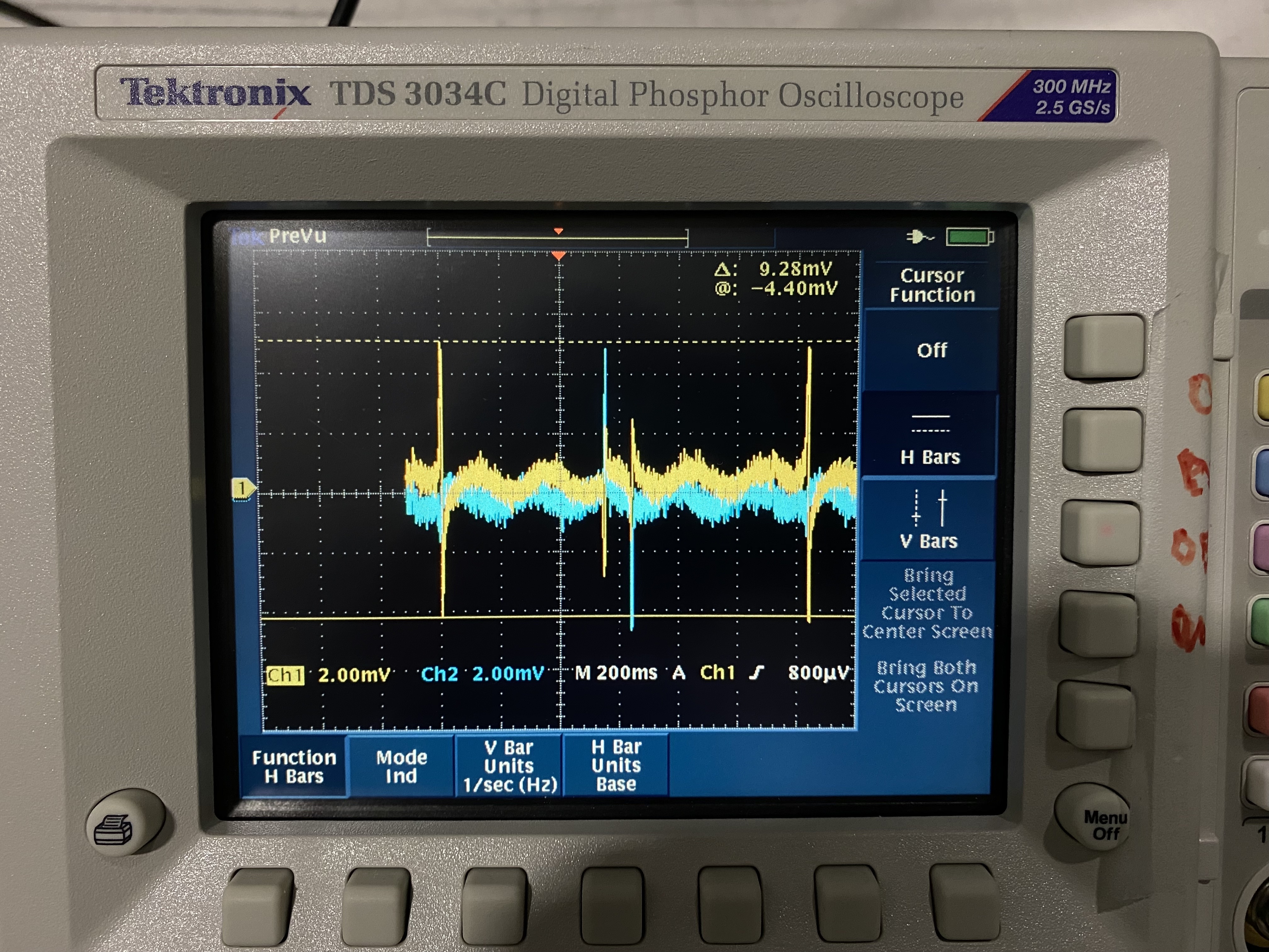
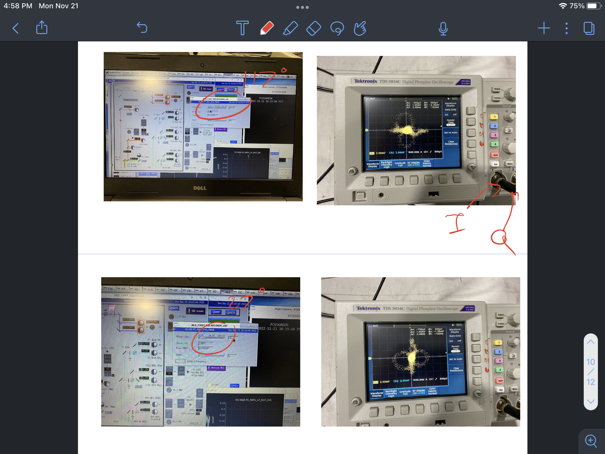
We measured 10 mVpp out of I-mon. Still low given the amount of power we think is hitting the diode (another alog to come). We saw the figure 8 on X-Y mode of the scope and were able to optimize the I and Q phase at 117 and 27 degree phase shift on the phase delay slider bar.
Initial results were confusing until we realized that the 80 MHz AOM in the FC path was using the straight through path rather than the deflected path. After a realignment the observed intermodulation products started making sense.
With a modulation index of 0.85 and ~0.2 mW on the FC REFL PD, we expect a pk-pk PDH signal of around 0.120 mW. With 0.2A/W, an RF transimpedance of 1.4 kOhm and a demodulator gain of 8, we expect something like 250 mV pk-pk on the I channel of the demod board. But only ~10 mV pk-pk were observed. More investigations needed.
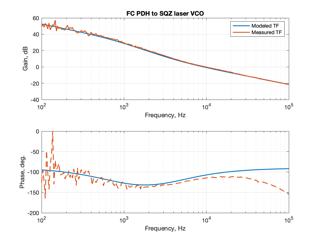
We thought the optic could be swinging to quickly that might cause the error signal to look smaller that it should. So, we took a transfer function and fit to it just to check. The modelled transfer function agrees with our observation. To fit the transfer function measured on the floor I gave the optical gain of 12 mV/FWHM(Hz). FWHM of the filter cavity is ~1.6 kHz. The modelled tranfer function didn't match the phase is likely due to me not including the pole of the VCO response. The VCO response probably stops somewhere around 100kHz.
We are missing at least a factor of 10 in error signal. The next thing to double check is the transimpedance on the FC refl diode.