Naoki, Sheila, Nutsinee, Daniel, Camilla, Vicky
We found green/IR co-resonance in the filter cavity today. First, following the good FC alignment from earlier LHO:66003, we just unlocked the filter cavity while the OPO was dither-locked in IR, and immediately, saw some refl dips (!!!!) on the SQZT7 PD looking at seed light. That is, the opo's transmitted IR power is retro-reflected from FC1, and already makes it through the VIP to our SQZT7 PD!
At the end of day, we optimized this red/green co-alignment. After the good FC green alignment earlier, we first made sure the seed power on OPO_IR_PD wasn't clipping (this is a long path, from opo-trans --> fc1 --> sqzt7). We had to move FC1/ZM3 a little bit in pitch and yaw, ~10s of counts. Then we adjusted in-chamber FCGS picomotors (H:M1, H:M2) to re-optimize filter cavity green alignment, at this unclipped red alignment. Screenshot shows filter cavity green trans + refl after pico-ing.
Naoki, Sheila, and I then tried to install the IR-TRANS camera on SQZT8 in the ham shack, with the goal of improving FC-IR alignment, but weren't that successful. Next time, we need to go with more dichroics / 1064 line filters to sufficiently remove green from the IR path on sqzt8. Also, it turns out we need more DC gain to stabilize our FCGS lock (see dtt, bulk of rms is from the low freq stuff). Specifically we probably should feedback to the M1 stage of FC2, and get all the M1/2/3 crossovers stable. With FCGS locked using both VCO (fast) + SUS (slow) feedback (can use SQZ_FC guardian's "GR_LOCKED" state), then the filter cavity can stay locked for a quite a while on green. In this state, we can scan or adjust the FCGS VCO around FC-IR resonance, but the low frequency vco drifts between red/green prevented us from holding the FC near red resonance for measurements.
Next week, we can 1) get mass feedback to the M1 stage of FC2 working to stabilize the low-freq red/green drifts, and 2) figure out a good metric to optimize FC-IR alignment. Based on LLO:62457, the FC green lock should be stable within a red linewidth with more optimal sus feedback. With a more stable green lock, we can measure cavity finesse (both ringdowns and pole/FSR) and take a closer look at fc losses.


The red FC TRANS was very hard to see by eye. Our initial alignment of IR at LLO only gave ~20 nW transmission power. The red/power contrast was so strong that we had to use dichroic + line filter to actually see red on camera. The clipped red light through FC2 was also strong enough to dominate 1064 PD readout if there's no iris.
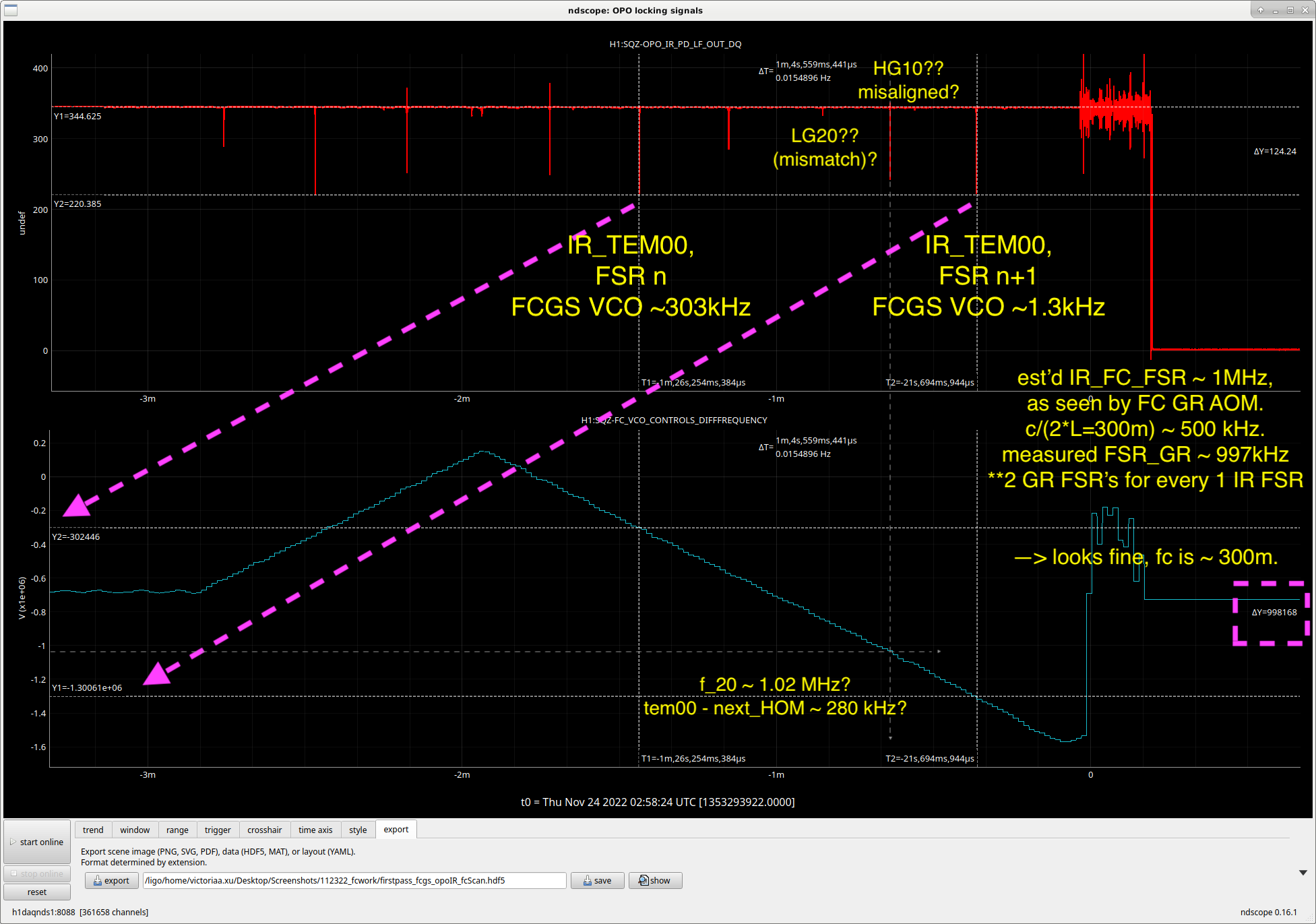
Sheila, Vicky - we can probably improve FC-IR alignment quite a bit, since the next biggest mode is likely from misalignment rather than mode-mismatch, see screenshot. With ROC1=flat, ROC2=512m, I'm calculating that the transverse mode spacing is ~140kHz. So scanning the GR VCO, we'd expect a frequency diff ~280kHz between higher-order IR mdoes; this looks compatible with what we see. The FCES IR_TRANS camera would help us be sure that the next big refl dip is from an odd mode. Even without it though, it may be worth continuing to align FC-IR with ZMs (while keeping up with the green H:M1, H:M2 pico's).
Naoki, Dhruva, Vicky
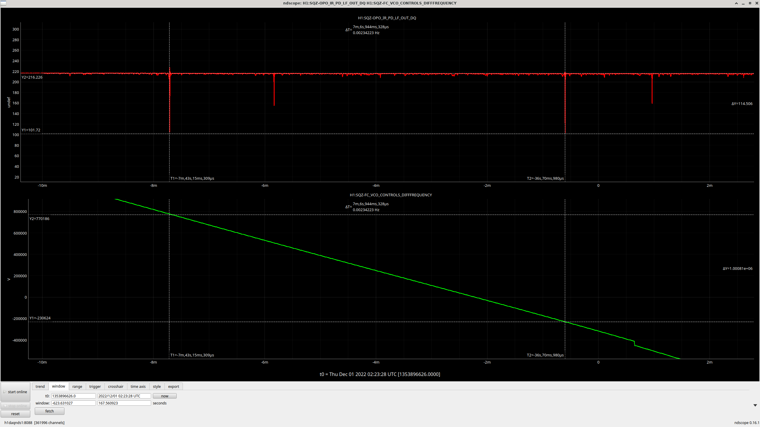
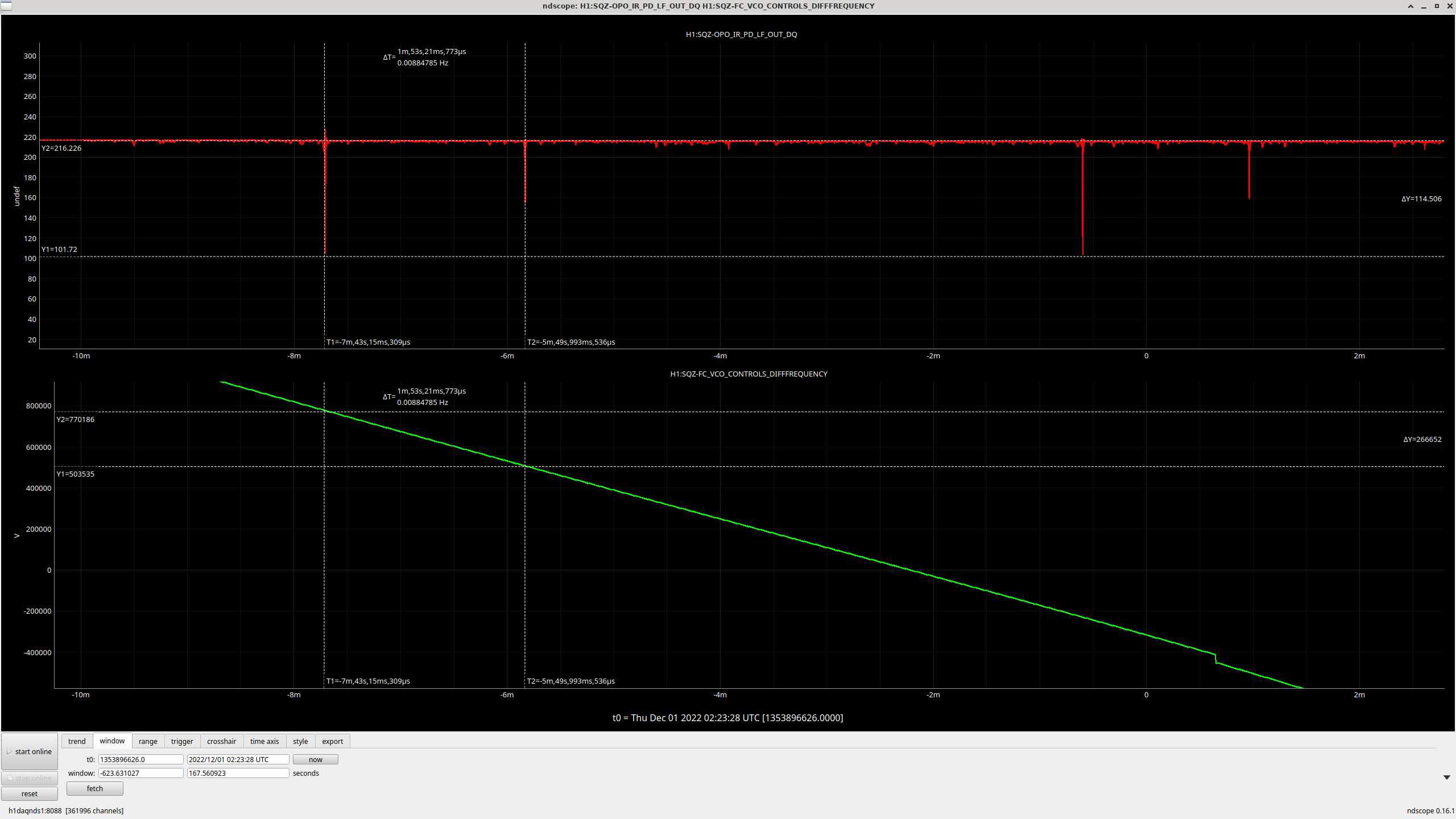
Dhruva aligned FC-IR better today, new/updated cavity scan attached. Here we are "GR_LOCKED" on the guardian, and scanning the FCGS VCO tune offset "H1:SQZ-FC_VCO_TUNEOFS" w/beckoff freq servo off. Highest peak is probably TEM00, next highest likely an odd/misaligned mode, LG mode-mismatch looks pretty good (ie don't see big donut mode!).
From refl dip, we're estimating around 78% mode-matching, 1-101/(101+216+156), for a refl dip down to 47% of its off-resonance value, so the dip is 53%.
Scanning script hacked together in /sqz/h1/scripts/sweep_fcgs_aom2_freq.py.