Note incomplete alog posted so people can see the plots, I will write the rest tomorow.
The first attachment here shows the actuator plants (in meters/count out of the lock filter) for FC2 (which is an HSTS with 20 bit DACs on all stages and no modified drivers). This shows that M2 is weaker than M3 and M1 at all frequencies, so it seems easiest to not use it in the suspension offloading of the filter cavity locking.
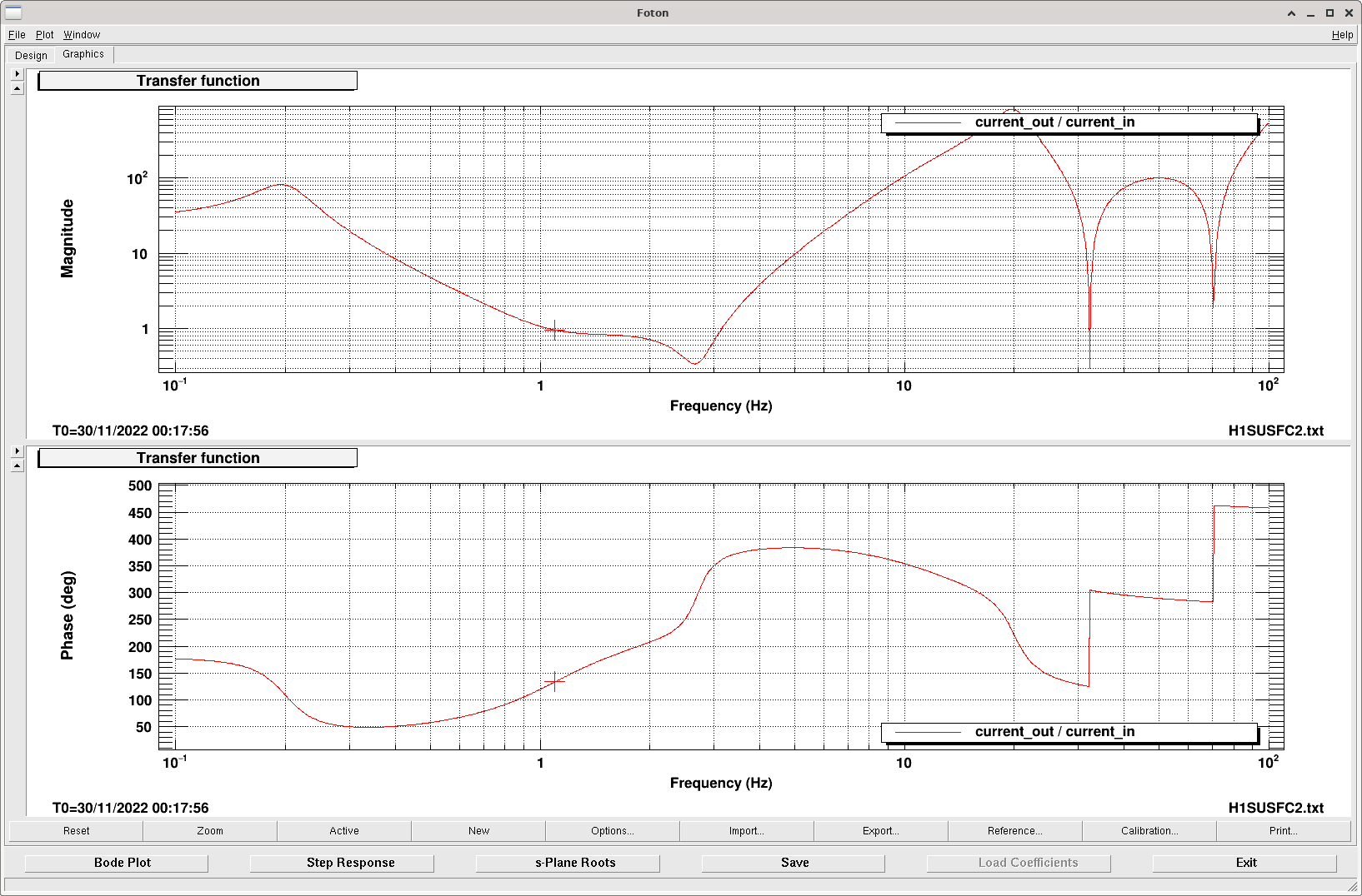
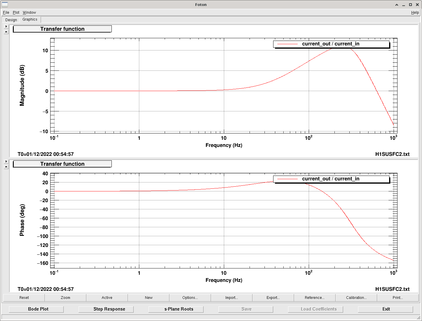
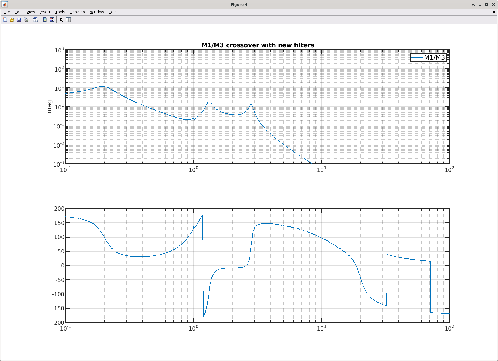
The next attachment shows the ratio of these gains to each other, if we want to use M1 + M3 we need to look at the M1/M3 ratio to design the M1 filters to have a stable crossover. The png attachment shows the filter that we proposed for MC1 (assuming that M2 is off and we keep the M3 filter the same as we used in 65981). This crossover is plotted in the 3rd pdf attachment.

Sheila, Naoki, Vicky, Dhruva
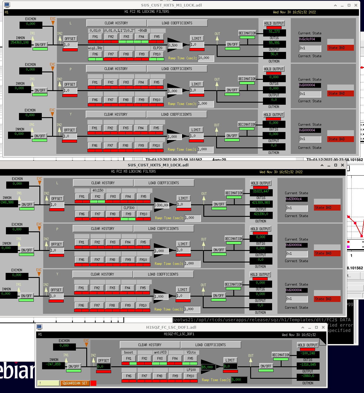
It turns out that this model wasn't all that acurate between 1 and 4 Hz. I will make a better alog soon showing the comparison of our measurements to the model. For now this alog we will juist document what we've done for now. The second screenshot shows the configuration of filters that we are using.
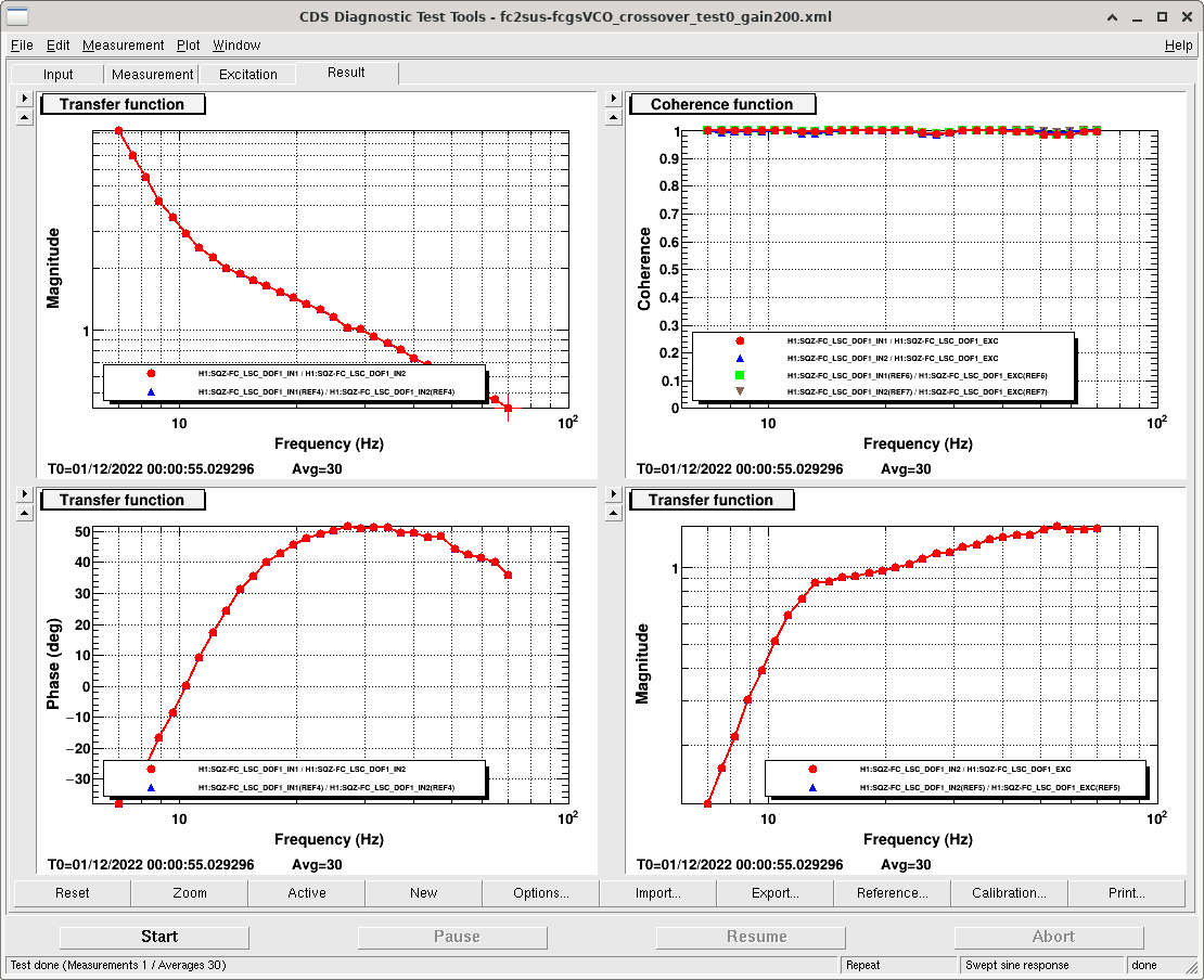
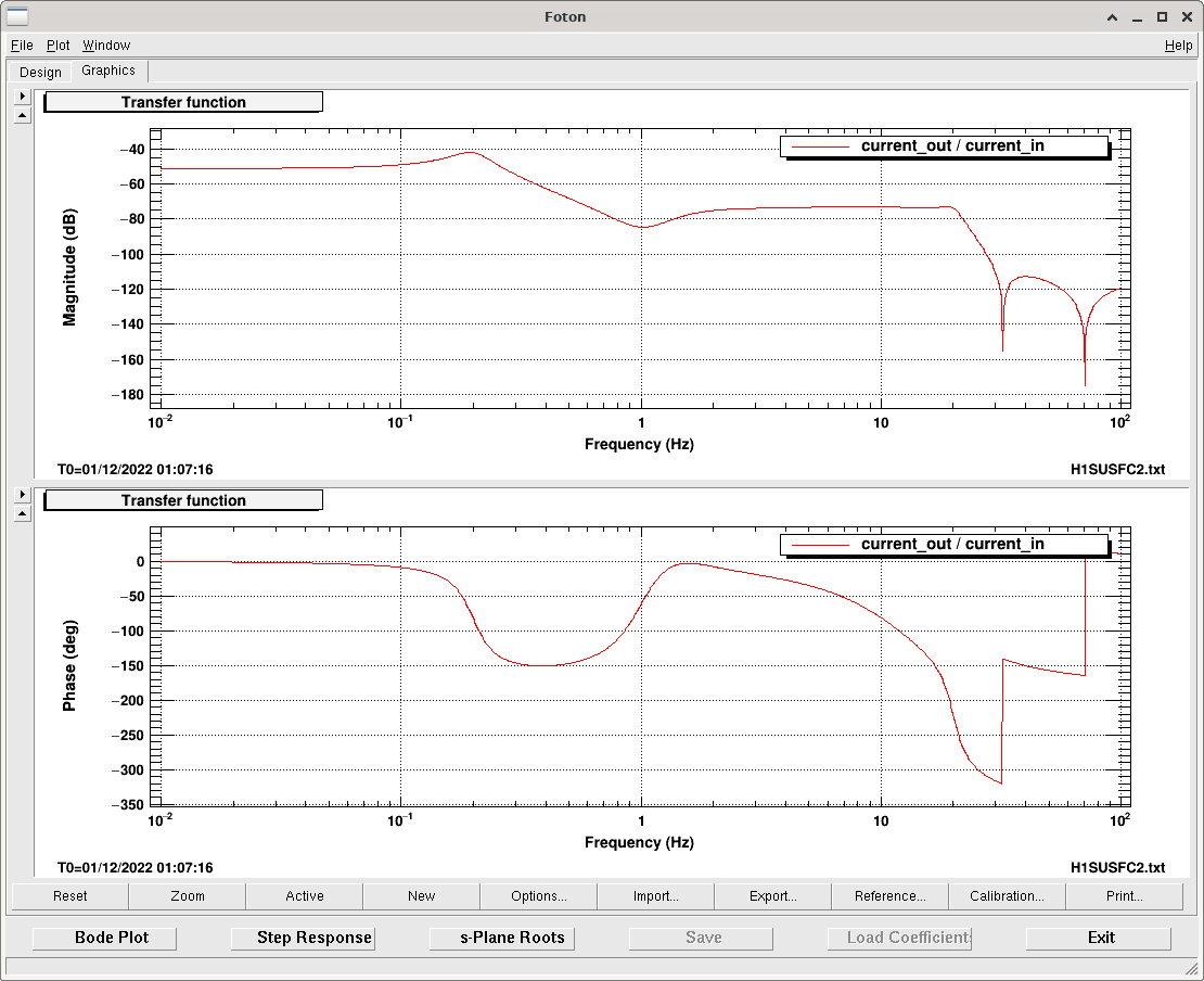
We are offloading the green VCO to FC2 M3 + M1. The first attachment shows the MC3 to VCO crossover, which is now at 30Hz. This is higher than the design requirements dcument calls for, but it made it easier for us for now to have the higher crossover. This is a simple filter copied over from MC2 feedback with a boost that we added, these filters (other than calibration factors) are shown in the 3rd and 4th attachments.
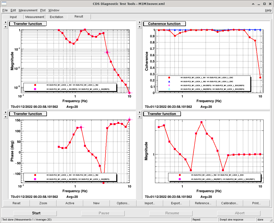
The M1/M3 crossover measurement is shown in the 5th attachment, it has several places where it is near unity, which isn't very efficent for offloading M3, but it is stable. Soon I will import this to compare to the model above, so that we can think about why the model isn't accurate and think about a better offloading. The 6th attchment shows what the model predicts for our currently in use filters. The final attachment shows the filters in use on M1.
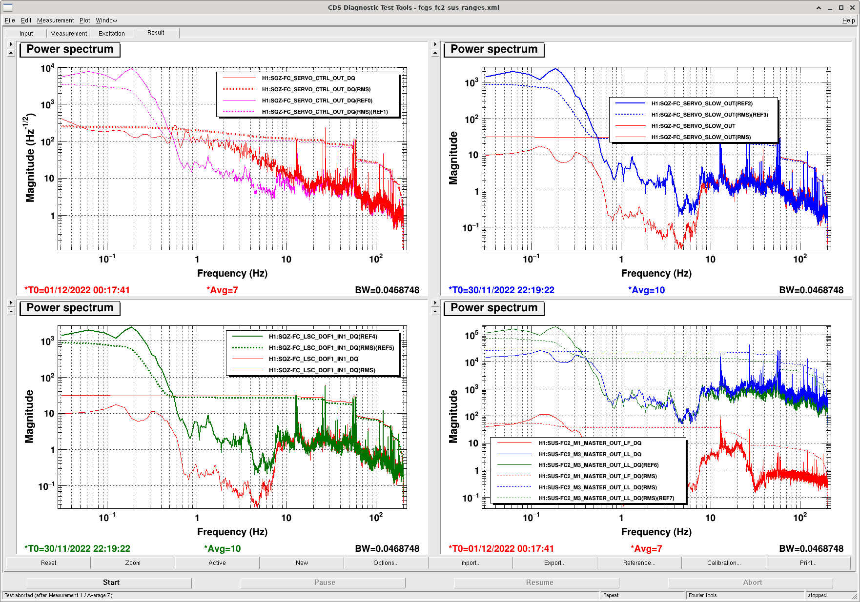
The last attachment shows a comparison of signals with the offloading only to M3 (and no boost), and with the current offloading on. We have plenty more range on M1, and a bit more range to spare on M3. FC_SERVO_CTRL is calibrated into Hz using the VCO calibration, so this offloading is giving us roughly 200Hz rms on the green VCO (so this should hold us to our lockpoint within 100Hz for IR). Further offloading could reduce this by a factor of 2ish, but beyond that the rms is dominated by the line features at 13Hz and higher frequencies.
I've added the measurements taken by exciting FC2 to these models, and added some filters that I left out above which allows these measurements to match the model. The main message here is that there seems to be a disprecancy in the HSTS model with what we are measuring for the M1/M3 crossover. This probably explains why we had difficulty implementing filters based on this model for FC2; years ago we had a simlar difficulty trying to improve the M1/M3 crossovers for PRCL and SRCL, I'm wondering if this is also the explanation for that. For PRCL and SRCL we have gotten away with having very low crossovers, for FC2 we will need a more agresive loop to meet the backscatter requirements.
- I'm treating the VCO feedback as a flat length to Hz sensor.
- At the time these measurements were made, we had the green slow feedback calibrated into Hz with VCO filter, and an anti-VCO filter in LSCFC DOF1. We've since turned both these off, but this model is using them.
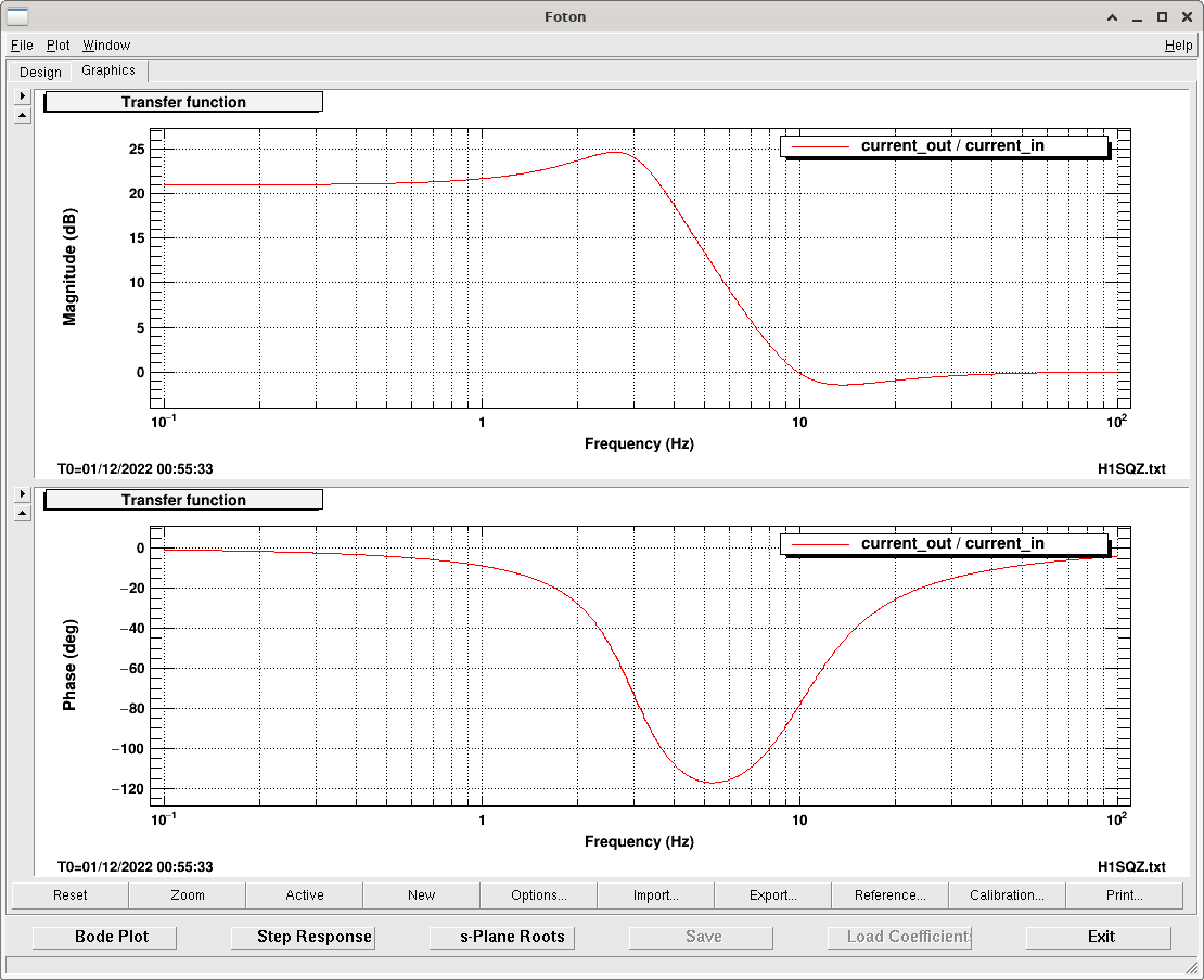
- The first attachment shows that the model matches the measurement well for the feedback of the sum of M1 + M3, which is mostly a measurement of the M1 response. To get the model to match I had to add an overall fudge factor of 82 to my Hz per length factor. We have a stable ugf for suspension feedback at 30 Hz, this could be pushed up to 60 Hz although Lee's modeling says that we don't ultimately want that high of a ugf for backscatter reasons.
- For the M1 measurements, the model doesn't match as well, which helps to explain why we had difficulty implementing filters based on this model. I've plotted 2 models, one is just -1 * ratio of M1/M3 including the M1 filters, which is what we usually think of as the crossover. The other model is a model of what we actually measure when we excite at M1 Lock: common * M1/(1-common * M3). These two models are almost the same, showing that it's a fine approximation to think of this measurement as the crossover in this case. This plot has no fudge factor, and the magnitude of the model looks about right, but the phase plot has a pretty big descrepancy.
- The last plot is -1 * M1 lock measurement / M1 lock filters, which should be the same as the ratio of the M1 plant / M3 plot. The plot shows the phase discrepancy that we see.
The measurements and matlab script used here (matlab because I know how to import foton and sus models into matlab) is in userapps/sqz/h1/scripts/FC2_offloading, svn commit 24039