[RyanS, Jenne]
There is interest in ensuring we have a functional spare TTFSS box, primarily so we have a spare, but also so we can think about testing modifications that would mitigate the 2.5 MHz peak that is causing trouble for the squeezer laser stabilization (alog 65675 summarizes the list of relevant alogs for that peak).
Below is a longer saga, migrating some findings from email threads to the alog. The summary is that the spare FSS box is close-to-functional, but we likely need to tune the notch for the "1.6 MHz" EOM resonance (which seems to be closer to 1.4 MHz in these spectra). Once we do that, I think we'll have a functional spare, and can start to think about modifying it to eliminate the 2.5 MHz peak.
A few maintenance days ago (Nov 15th) RyanS and Jason went in to the PSL to plug in the spare FSS box, but found that it was not able to lock the refcav without oscillating. The spare we have is S1107799. We seem to have neglected alogging that work, but I copy in Jason's findings from an email thread so it's in the alog:
- In pursuit of the 2.5MHz issue that’s been limiting SQZ performance and has been traced to the PSL FSS, Ryan and I tested our spare PSL TTFSS box (SN LHO03, e-traveler at S1107799) yesterday (this was in advance of possibly trying to add another notch to block this 2.5MHz line, need an operational spare first; eventually I’d like to see us upgrade to a newer generation TTFSS, but that’s a longer term project and this issue is hurting SQZ now). While we were able to lock the FSS reference cavity with the spare box, the loop was very unstable.
- · Loop constantly in oscillation
- Despite all available adjustable gains being at their minimum, the control loop was oscillating wildly, jerking the NPRO PZT around much more than during the “usual” oscillations we see
- Changing loop gain had no effect on this oscillation that we could see
- PDH MIXR Vpp very high
- We usually see a MIXR Vpp < 0.1V, and consider the loop to be oscillating with Vpp > 0.5V
- With the spare box we were seeing MIXR Vpp of ~22.2V
- The MEDM readback was pegged at this value and not moving/changing, maybe something blew and/or railed on the high side in the MIXR circuit?
- Pockels cell (the so-called ‘Ultra Fast’ path)
- During normal operation we usually see a Pockels cell drive voltage of a few volts, sometimes around 10V if the gains aren’t tuned properly
- The spare box was trying to drive the PC with 60V, way more than I’ve ever seen with the various incarnations of the aLIGO PSL; this was with all available adjustable gains at their minimums
- · Loop constantly in oscillation
Marc was able to test out the spare on the bench, and found that some parts were bad. Again, copying findings from the email thread so they are in the alog:
-
Here is a rundown on what I have tested so far.
-
Power rails look good.
-
I checked the modifications and everything looks to be in place.
-
I attempted to perform the transfer function described in figure 3 of the conversion document, did not look too good. Conversion doc giving steps to convert eLIGO TTFSS to aLIGO: T1100119.
-
I stepped through the circuit with a 1MHz signal at 0dB, everything looked good until I got to the PA85 which had a very odd output, we thought it was bad.
-
We replaced the PA85, looked bad still, so I reduced the drive strength of the input signal all the way down to -60dB and then it looked like a sinusoid.
-
-
The gain on the PA85 is very high 30x or 15dB, not counting what the daughter board D1100371 is doing.
-
-
I just looked it up the daughter board applies 20x more gain, so 50x total gain on the PA85 chain, where the other chain has 1x gain.
-
Filters are not well documented but we can figure them out. So far I do not see any source of oscillation.
-
The MIXR signal looks good at TP3.
-
The mixer chip was not letting any signal through, we replaced it with a spare mixer chip, and now it looks to be working.
-
Old mixer chip JMS-1H, new mixer chip JMS-1 (didn’t see much difference between these maybe ROHS?)
-
-
I noticed the SMA RF input center pin is a bit loose, I bent the conductor a bit so we could get a connection, just be aware of this if you do not get a good connection, the LO port is fine.
-
I did adjust the trim pot to center the signal (before we found the issue with the mixer), so you may need to trim the OP27, though I believe it is trimmed correctly.
After Marc replaced those parts, Ryan and I went back into the PSL this morning to give the spare another try. My current verdict is that it doesn't not work. We were able to lock the reference cavity with the spare FSS box, although it spent a lot of time oscillating before it seemed to realize that it was locked, and engaged the Temperature loop. Once the Temp Loop was engaged, things seemed to be quiet and pretty normal, and we were able to take spectra and open loop measurements.
- The mixer outputs seemed to have sensible values, less than 0.1 Vpp (this is better than the last try before the mixer was replaced. good)
- The EOM output was very high, ~62 V, when the loop was oscillating, even if the common and fast gains were at their lowest slider values. This seems to be roughly the same as last try.
- When it was oscillating, the autolocker wouldn't totally recognize that the refcav was locked. If we waited a long while (~minutes), it eventually recognized it was locked, and turned on the temperature loop, and stopped oscillating, and the output to the EOM would go down to a few V. I don't understand the sequencing of the Beckhoff automation, and I didn't notice which thing happened first, so I don't know if it's the temp loop coming on that settled things, or if things settling allowed the temp loop to come on.
- Even when things were settled, we couldn't increase the loop gain to our nominal ~300 kHz UGF without causing the output to the EOM to go high (I was trying to keep it below 3 or 4 V, although with our normally-in-use box it doesn't even usually get that high). So, the spare box, as it currently is, can't give us the high bandwidth that we need.
- The 2.5 MHz peak is still present. Not a surprise.
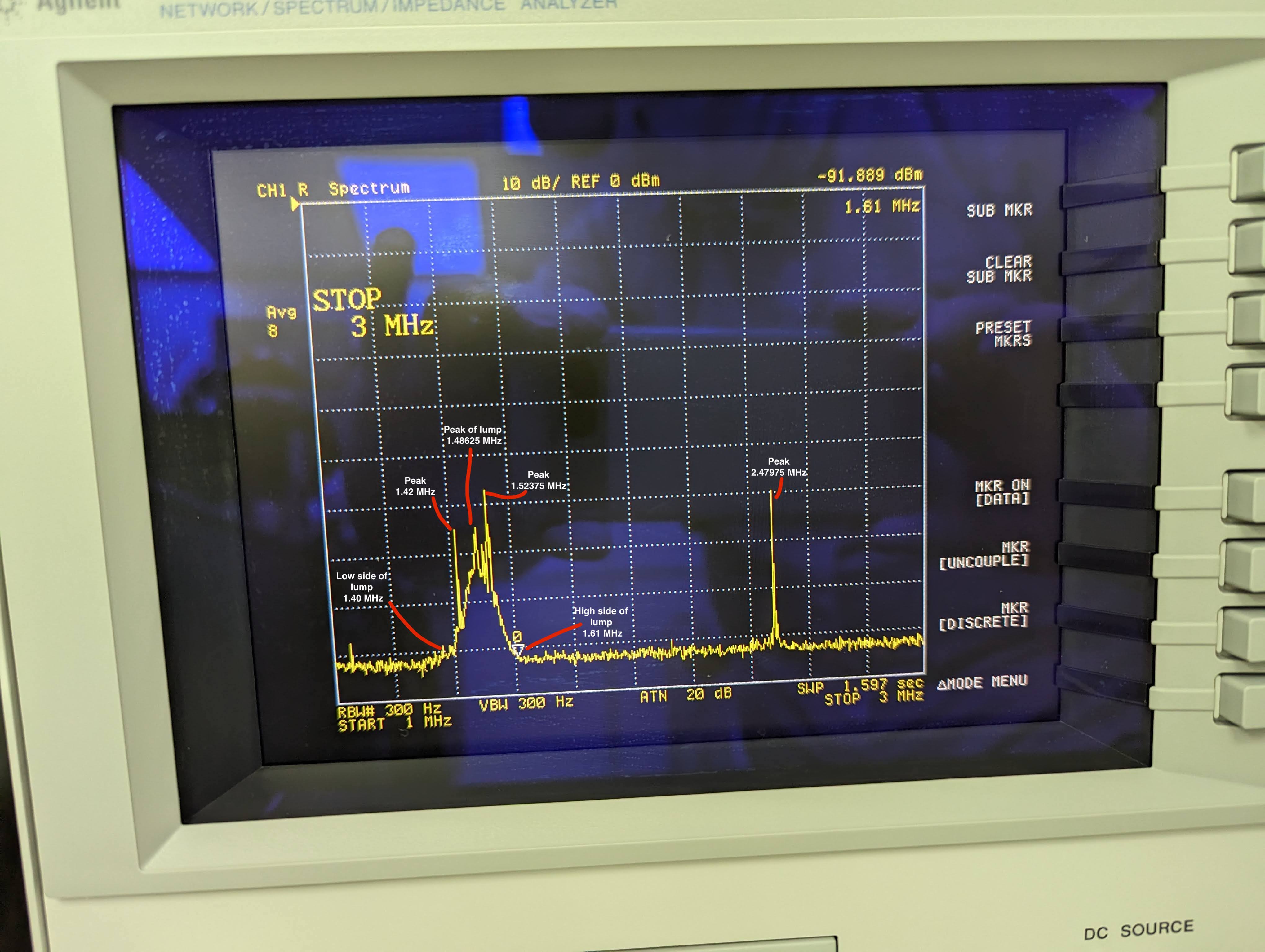
- There is a broad lump and a few narrower peaks around 1.4 MHz. I assume that this is present because the spare box hasn't had its notches tuned for our in-use EOM. Tuning this notch should be our next objective with this box, so we can try swapping it in again.
Attachments:
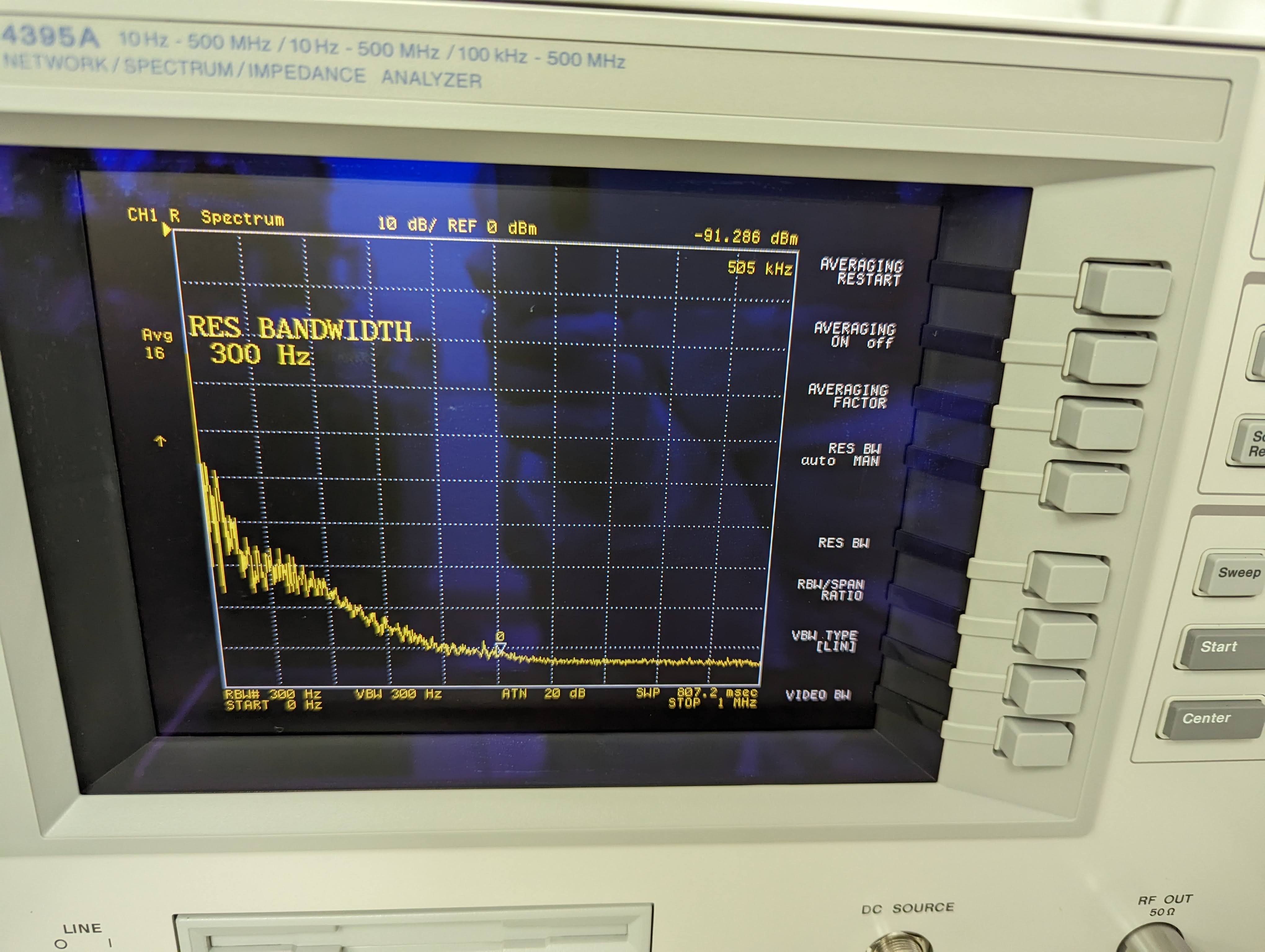
- IN1 spectra when refcav was locked, but EOM output voltage still very high. Clearly an oscillating mess.
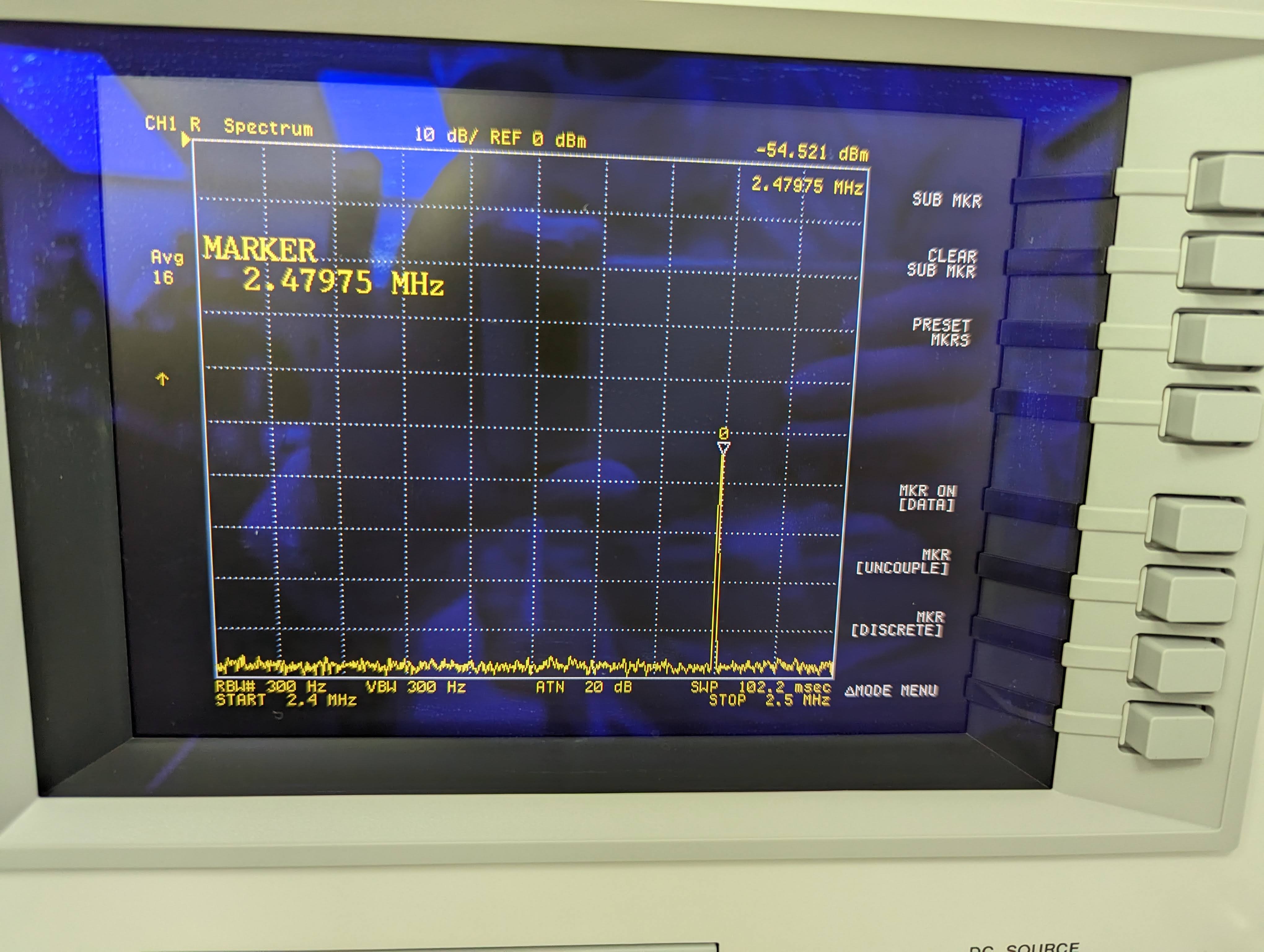
- IN1 spectra when refcav was locked, but not oscillating. Frequency of "2.5 MHz" peak is 2.47975 MHz. (This is the frequency we'll design an additional notch to take care of). This was taken when the common and fast gain were both very low, but I don't think that should affect the peak's frequency.
- Spectra including ~1.4 MHz lump that is probably not notched properly in this spare box, as well as the 2.5 MHz peak. I've noted a few various frequencies that we measured, to aid in future notch designing.
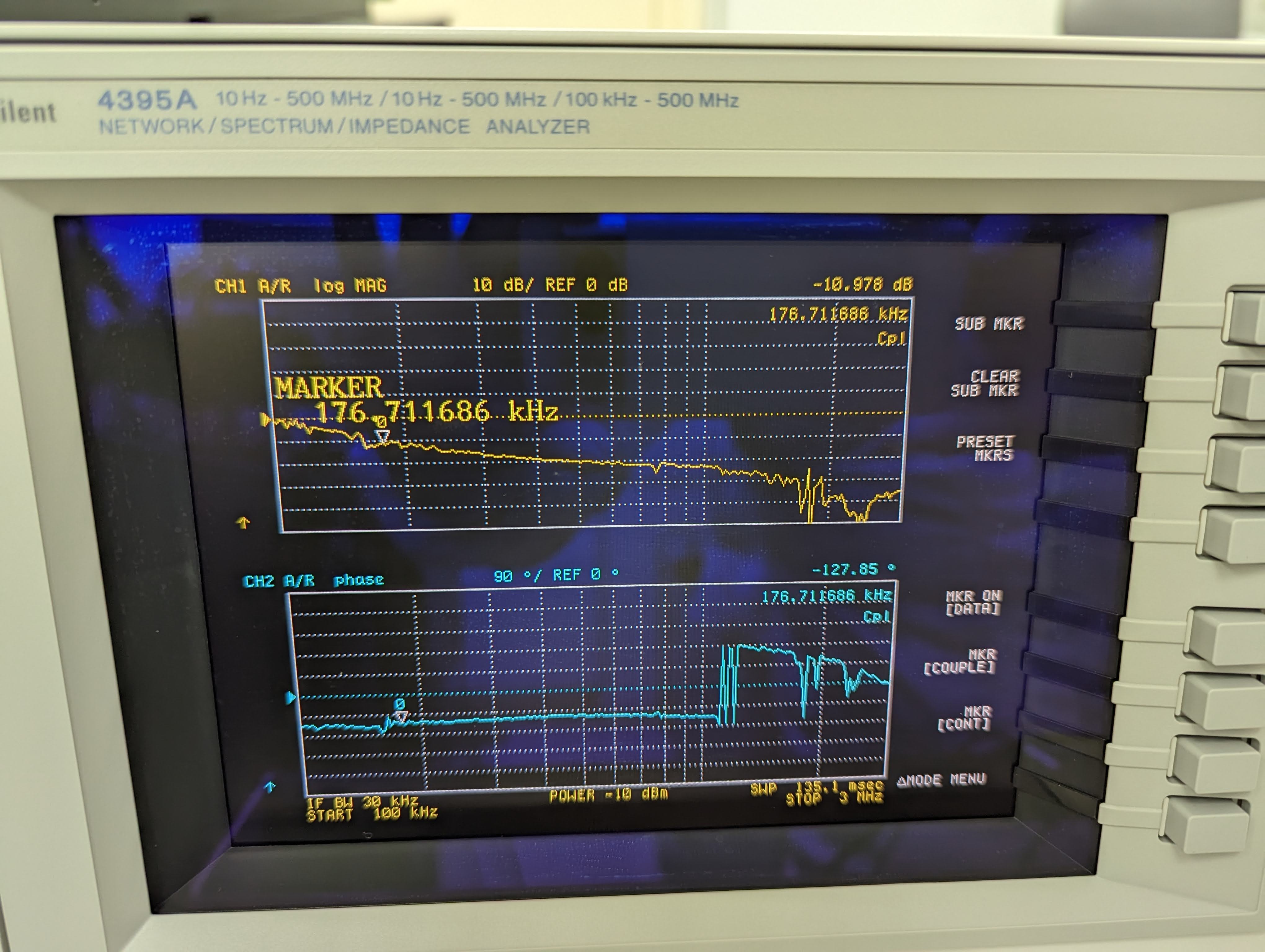
- Photo of open loop gain measurement when FSS was not oscillating. The Common gain was at 9 dB and the Fast gain was at 0 dB at this time. The UGF is about 175 kHz, when our nominal should be closer to 300 kHz. As this is directly measured from the FSS box, we must recall that there is the annoying -10 dB in the test point, so that actual unity gain is at the -10 dB point on this plot.
Update on the spare TTFSS box, SN LHO-03. Yesterday Marc, Ryan S., and I took a look at the notch filters. We found the 35.7kHz notch in the Fast path to be properly tuned, so changed nothing with that filter. However, the 1.7MHz EOM resonance notch in the Pockels cell path was found to be at roughly 5.5MHz (!). To get the notch down to the ~1.7MHz it's supposed to be, Marc replaced the inductor in the notch filter (inductor L2 on the circuit drawing) with a 120µH inductor. Adjustable capacitor C50 was then tweaked to get the notch at ~1.7MHz. With that in place we now plan on testing the spare box this upcoming Tuesday (1/17/2023).
Why was the notch so much higher than it was supposed to be? Marc figured it out. Turns out inductor L2 was not what the drawing said is was. L2 is listed as a 220µH inductor, but upon running the math for the notch filter and checking the inductor itself Marc found that it was actually a 10µH inductor. Mystery solved. Since we put in a 120µH inductor instead of the listed 220µH one, the Q of the notch is now lower than it originally was (12.7 vs 23.5). Turns out this may be a good thing, as alog 17885 indicates that a lower Q notch at the EOM resonance is more desireable than a high Q notch. We'll find out Tuesday when we test the spare box.
Another update. Yesterday we sat down with Daniel to gameplan how to get the new 2.5MHz notch hacked into the PSL TTFSS. There is not room for extra notches, so some creativity was required, and it was decided to go ahead an install the 2.5MHz notch so we could test that on Tuesday as well. In the end, Marc removed the GND testpoint TP26 and soldered the GND port of a 4.5-65 pF adjustable capacitor there. A 120µH indcutor was then installed on the relevant port of the adjustable cap and a small wire used to wire this notch filter to the relevant point in the PC path of the TTFSS (see area cirlced in red on attached picture, with the small white wire going to one end of inductor L2). We then powered up the spare TTFSS and tuned this new notch to the frequency identified in Jenne's above pictures (2.479MHz). We will also test this new notch and tweak as necessary this coming Tuesday.
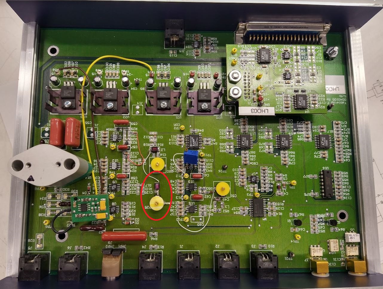
Apologies, that should be TP25 that was removed to install the new 2.5MHz notch, not TP26. TP26 remains in place.