Yesterday and today I made measurements of our soft yaw loops to determine why they are causing us such trouble at high power. I think our overall goal is to get to a point where we can turn them off, but in the meantime we need to stabilize them.
Both soft yaw loops are engaged at Power 25W. Yesterday we used a CSOFT Y gain of 5, but today our lock stability at 60W is thanks to a CSOFT Y gain of 20. All of these measurements were made with the new CHARD Y loop.
I have attached plots of the open loop gain of CSOFT Y and DSOFT Y at 25W, 50W and 60W. The gain for DSOFT was 100 for every measurement. These plots show that with increasing power, the peak of the loop shifts to lower frequency, and the phase slowly degrades. This is similar to the effect of high power in the soft pitch loops.
Also, the 25W and 50W measurements were made at the high bandwidth ASC state, while the 60W measurement was made at low bandwidth. It would probably have very little effect on these loops, but the amount of gain in the CHARD Y loop at 0.45 Hz changes.
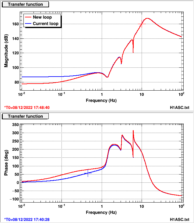
Stefan and I looked at the current control filter, and have considered changing the zero at 0.3 Hz to 0.1 Hz. The resulting change to the filter can be shown here (we scaled the gain of the new filter to match at 10Hz): comparison plot. This would give us ~20 deg more phase and only 2 dB of gain difference at 0.45 Hz.
It might be worth making this change in all soft loop control filters. We will test this change after the next lockloss.
I have also copied my measurement templates over to userapps, into asc/H1/templates/ into the respective ASC dof folder. These were broadband excitation olg measurements.


The control filter change for soft yaw caused a lockloss with an oscillation at 0.56 Hz while we were in move spots.
The first two plots I am attaching here reiterate information already in this alog, but I have also included the close loop suppression of the soft loops. I also rescaled the gain of the 60W measurement of CSOFT Y by 0.25 so the open loop gain has the same loop gain as the 25W and 50W measurements (CSOFT Y and DSOFT Y).
I have tried modeling the soft yaw loops. I am really curious about what is happening to the phase around 0.4 Hz where at 25W is appears stable, but then as we move to higher power it degrades and moves through zero. However, this feature is not evident in the models I have created. I overlayed my open loop gain measurement with the model, for CSOFT Y and DSOFT Y. In this model, I include the M0 suspension stage as well as L2 and L3. For the CSOFT model I used 100 kW of power for the 25W model, 270kW for 50W and 330 kW for 60W. For the DSOFT model I used 120 kW, 290 kW, and 350 kW respectively. I think these two measurements were far enough apart in time that perhaps there was some thermalization that increased the circulating power.
My guess for the phase discrepancy is that there is some sort of cross coupling in the loops that contributes to the loss of phase. I had a similar problem modeling the soft pitch loops.


I often cite these measurements as some evidence that the right half plane poles in the soft loops are spot position related. I looked back at the DTT used for the CSOFT Y measurements I plot in this alog and trended the guardian state for the time when the 25W measurement was taken (GPS time 1354494219). Indeed, the measurement was taken while we were at "Power 25W", which is the state before Move Spots. For further confirmation, I also trended the A2L gains (which we use for spot position). When the beam is centered the P2L gains should be 0.85, and Y2L gains should be zero. That is indeed the case here for the 25W measurements. I don't understand the physical mechanism here, but this is an interesting data point for us while we try to understand what is going on with the ASC loops and suspension plants.