Dhruva, Camilla, Sheila, Lee (remotely), Vicky
1) Today we optimized FC-IR mode-matching and checked that with optimized FC-IR alignment, we do not see noticeable sqz beam clipping. Main thing we did was adjust ZM2 PSAMS from 80V to 90V (strain gauge moved from 3.4V --> 3.55V), which noticeably relieved a little yaw-clipping. To check clipping, with OPO dither-locked on seed, we awggui-dithered ZM2 pitch + yaw until we saw clipping on OPO_IR_PD, then backed off the dither amplitude until we saw a plateau which we loosely interpret as no clipping (no power fluctuations correlated with dither frequency). Worth noting, we first used ZM4/5 (after VIP) to center the beam on OPO_IR_PD (on sqzt7), this was important; also, when we checked clipping based on the in-vac QPD's for FC_WFS, at some point we missed the QPDs so it falsely looked like clipping, but this just means we will likely need to pico the RLF-QPD's later on. The amplitudes over which we see a power plateau on OPO_IR_PD (or WFS_Q_SUM) help estimate how much alignment clearance we have from clipping, it looks at least tens of counts in ZM2 P/Y.
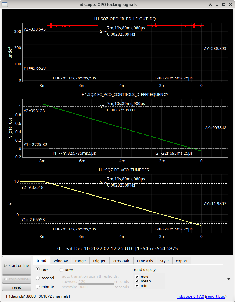
Dhruva optimized alignment as we went. First, with ZM2 bumped up to 90V, mode-matching looks basically the same as our most recent scan two days ago 12/7 when we moved towards FC2 optic center. Today we first saw basically the same odd misalignment peak at 280kHz away on the green VCO (aka, 140kHz away for red, 1 FC-IR transverse mode away). Dhruva realized that the mode-scan direction (freq-->fc length) is reversed due to the recent FCGS AOM cable swap on 66217 from 12/6, so this scan makes sense. This showed us there was room to improve IR alignment, because we want to check that an optimally-aligned FC-IR beam does not clip in ham7.
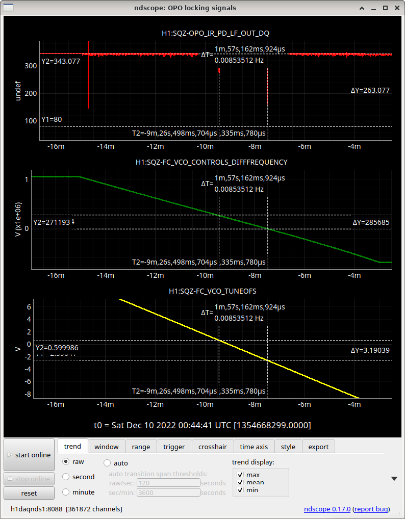
Dhruva then aligned ZM2+ZM3+FC2 P/Ys, and he and Camilla spent some time pico-ing on H:M1 and H:M2 to track GR alignment. We now have this very nicely aligned and matched mode scan for filter cavity IR!! We now have 1064 line filters so we can measure mode-matching in IR transmission next week.
Helpful reference points from this mode scan:
- FC-IR 500kHz FSR = 12 V on GR VCO tune offset. This means locking on the other GR FSR will make the nearest IR mode 6 V away in either direction; there are 2 green FSR's per 1 red FSR (green color is half of red).
- FC-IR 140kHz Transverse mode spacing = -3.2 V on GR VCO tune offset. So if unsure whether on e.g. HG01 or fundamental, can try moving tune offset down by 3.2V to check.
2) RLF is now set to 102.620 kHz, a first step to setting the filter cavity detuning within a cavity pole of the IFO carrier frequency. This is necessary to do real fc backscatter tests, to see whether FC's resonant backscatter, at our current level of residual filter cavity length noise, is tolerable. Lee and Sheila helped us figure out what to do. So to start getting the FC detuning close in preparation for backscatter tests, here is what we did:
* OPO dither-locked on seed, looking at OPO_IR_PD on SQZT7. FCGS locked on green.
* We first tuned the FCGS VCO frequency to find seed (aka carrier) resonance, and noted down the GR VCO frequency (easier, its tune offset) for carrier resonance (seed IR refl dip). Keep locked on same FC-green.
* Re-locked OPO on LOCKED_CLF_DUAL (both green pump and clf).
* At this same FC-GR length where the seed is resonant, we moved the RLF frequency to bring it back into resonance, looking for resonance in the RLF-CLF error signals (FC_WFS_{A/B}_SUM_{I/Q}_OUT).
With our re-alignments today, we will need to re-align the sqz beam to the IFO as we set up for backscatter tests next week.
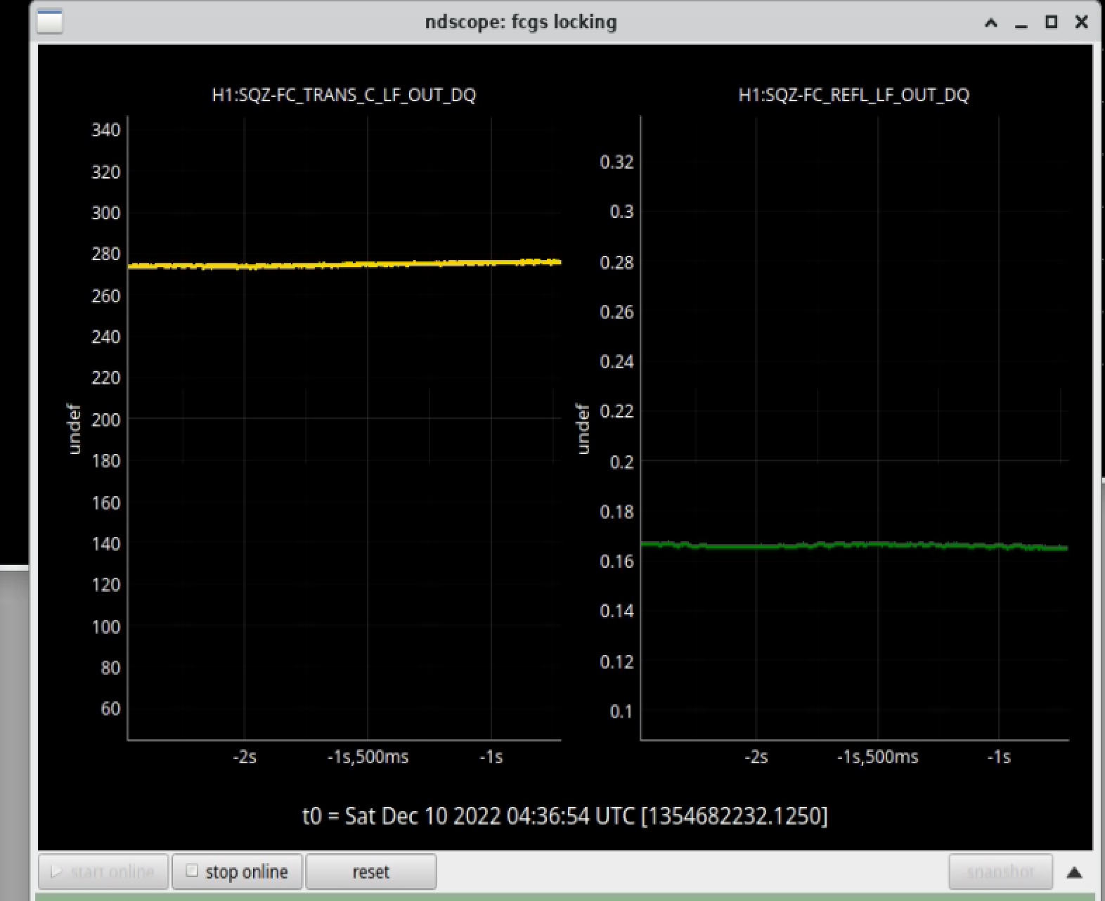
After all the ZMs and FC2 were aligned to maximize IR coupling to the FC, I spent some time trying to move picomotors. FCGS trans is now around 275 counts (increased by a factor of ~2.5) and the 01/10 mode is considerably weaker. This should make locking the FC a bit easier
Not sure this VCO calibration hangs together, see e.g., alog 65175. The voltage response at the EPICS slider is a factor of 2 lower than at the differential analog input.
This type of VCO isn't completely linear over the full range, so specifying the frequency, in particular, the difference from 80 MHz (1st AOM) should be more reproducible. The frequency is read back with a GPS synchronized frequency counter, so it should be accurate. The channel H1:SQZ-FREQ_FCGREEN can be used for this.
As a reference the FSR was measured here with f_FSR = 503,387.5 Hz.
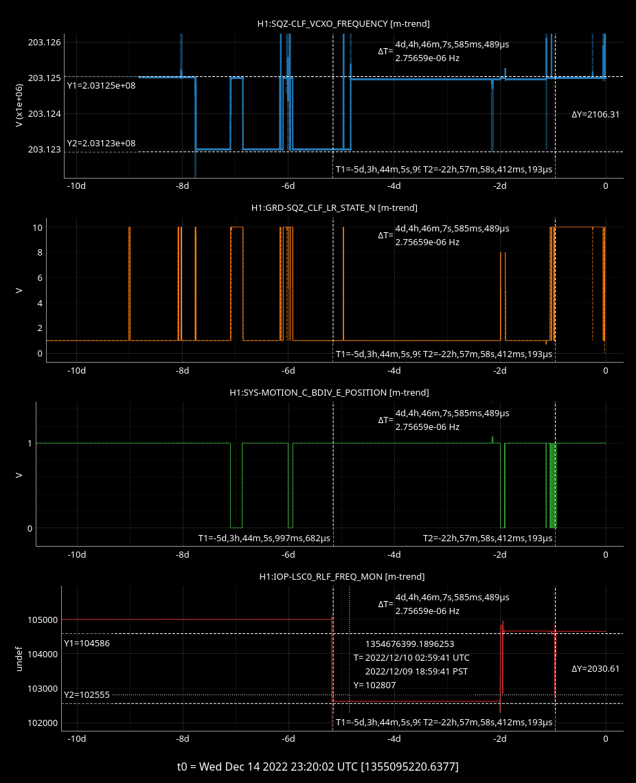
RLF Frequency is only meaningful with the CLF_RF6 loop locked. This is important as we now begin monitoring the stability of the FC detuning from IFO carrier. The FC detuning is largely set by the RLF frequency (e.g. see H1:IOP-LSC0_RLF_FREQ_MON).
Without CLF_RF6 locked, the CLF VCXO frequency is not servo'd to 203.125 MHz, so it drifts. See attached trend: when CLF freq was -2kHz from nominal (blue), the CLF_RF6 loop is unlocked (orange trend when GRD-SQZ_CLF_LR_STATE_N != 10). The GPS synchronized readback of the CLF frequency (H1:SQZ-CLF_VCXO_FREQUENCY) shows drifts. But CLF freq doesn't drift when CLF_RF6 loop is locked, so RLF freq is only a meaningfully indicator of FC detuning when CLF_RF6 is locked. On 12/9 (original alog) we set the RLF frequency without the CLF_RF6 locked, leading the CLF_VCXO to read back -2kHz, ie below its nominal 203.125MHz. This is why the injected IFO-FDS from 12/14 (green bdiv=0) uses an RLF frequency about +2kHz higher from this initial RLF freq (when CLF_RF6 wasn't locked).