J. Oberling, R. Short, M. Pirello
Previous alogs here.
Today we again tested the PSL spare TTFSS box. Very similar to the previous test from December, the box would lock the RefCav but sat there and oscillated for a couple of minutes before settling down and turning on the FSS temperature loop. While it was oscillating it was driving the Pockels cell at ~65V, but once calmed down was a more sedate 0.5V or so. And just like with the December test, we could not raise the gain enough to get the FSS UGF to the ~400kHz it usually runs at. With MEDM slider gains at their minimums we had a UGF of <100kHz, and the best we could get before things got angry was ~165kHz UGF. Also, as we were raising the FAST gain we began to see small, regular peaks in the NPRO PZT signal at around 5dB FAST gain; more FAST gain did not improve the behavior or make it worse, but it did go away when we lowered the FAST gain back below 5dB. More investigation into the gain of the spare box is required before we can call it a working spare.
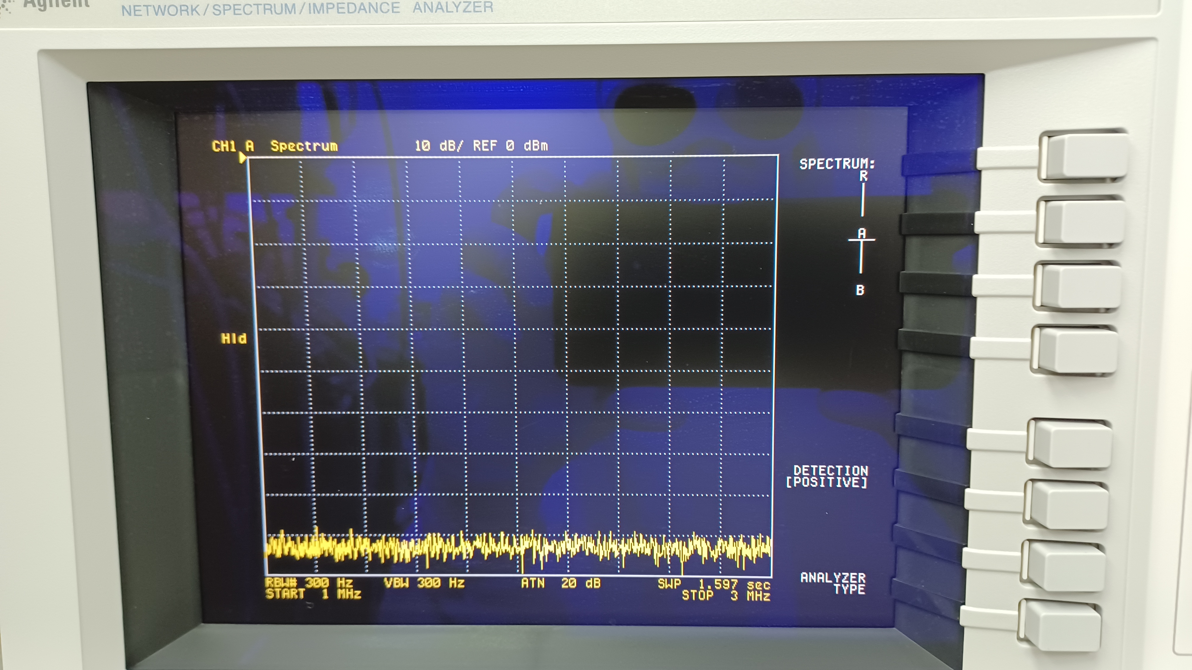
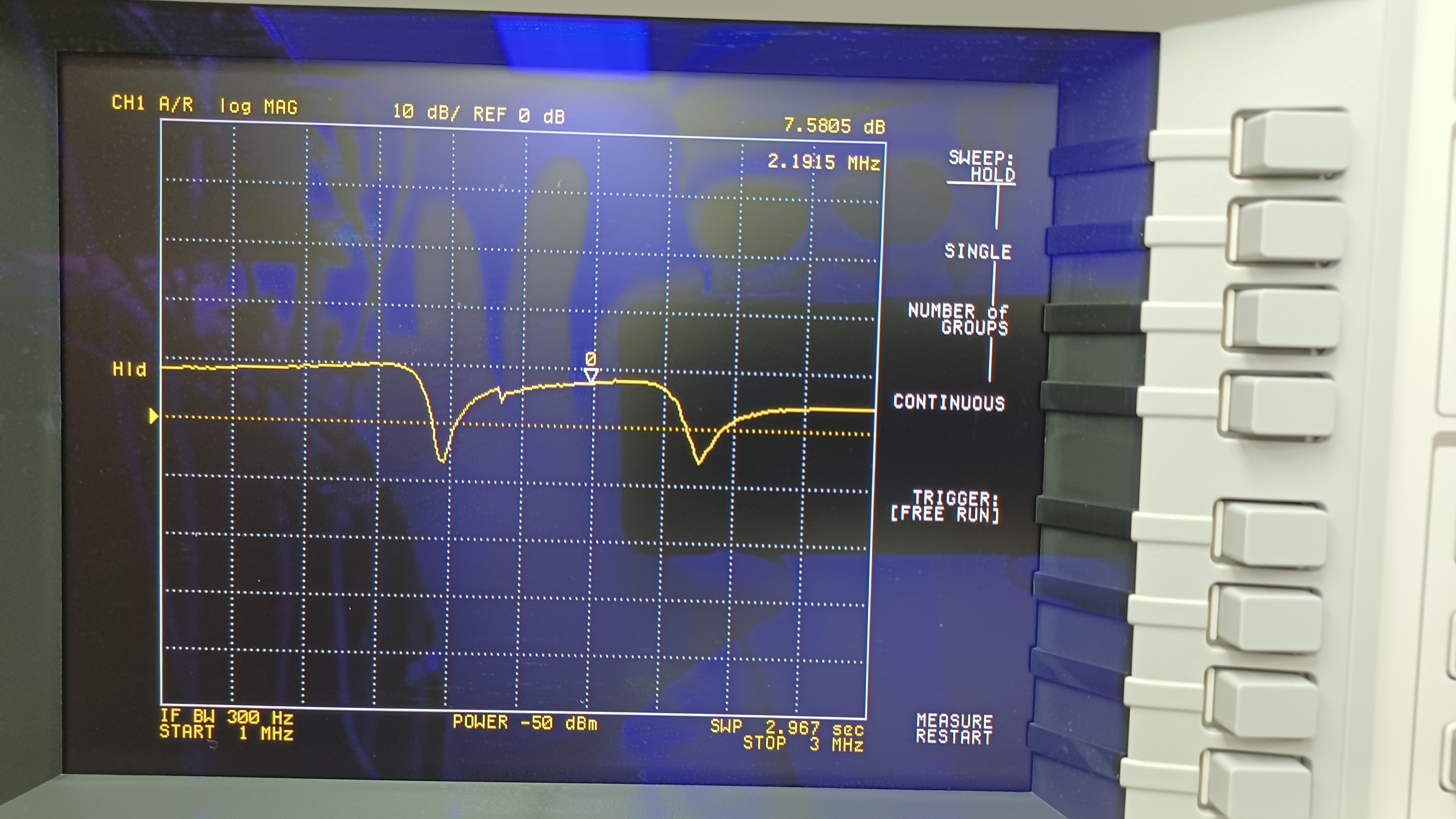
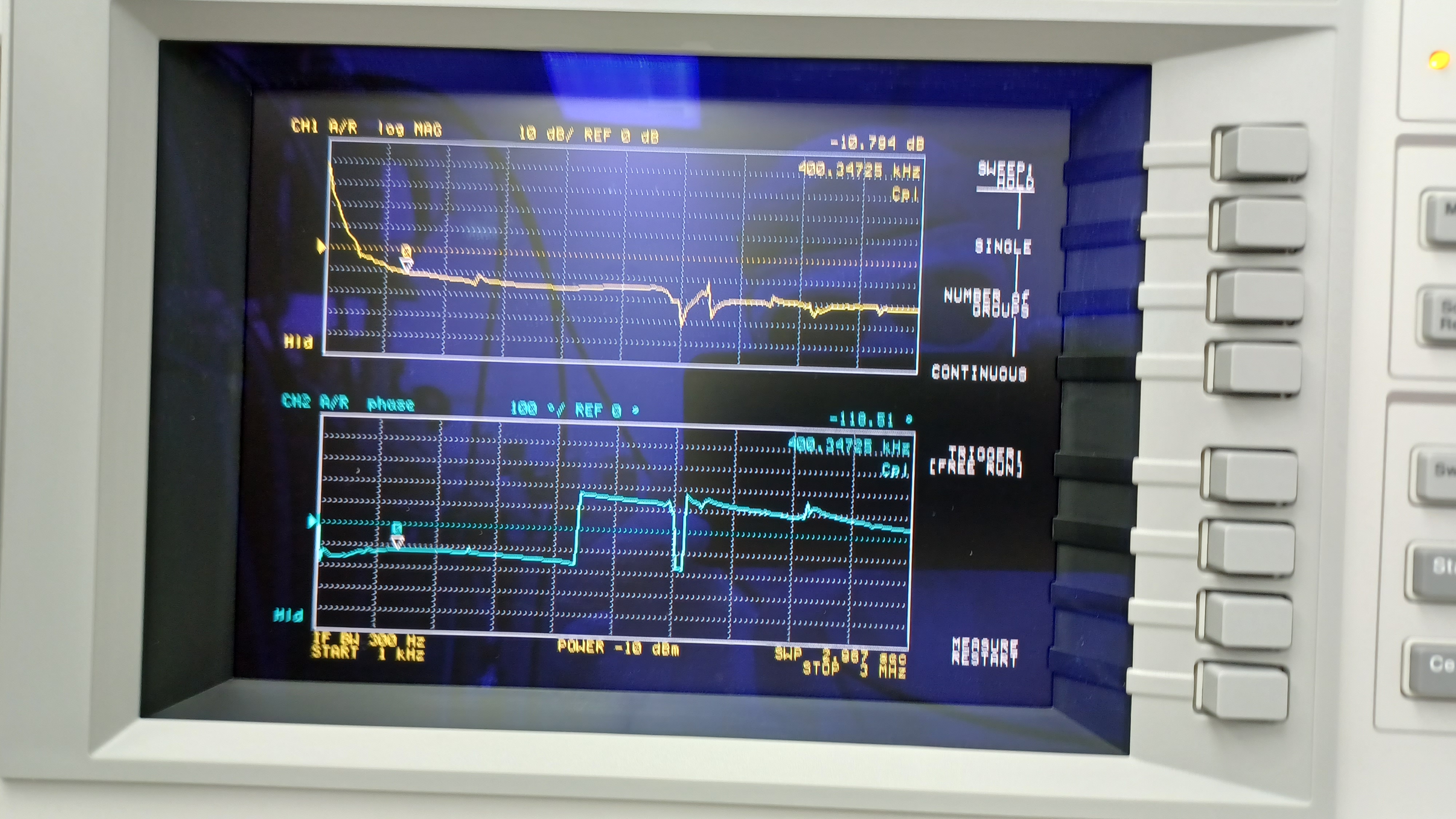
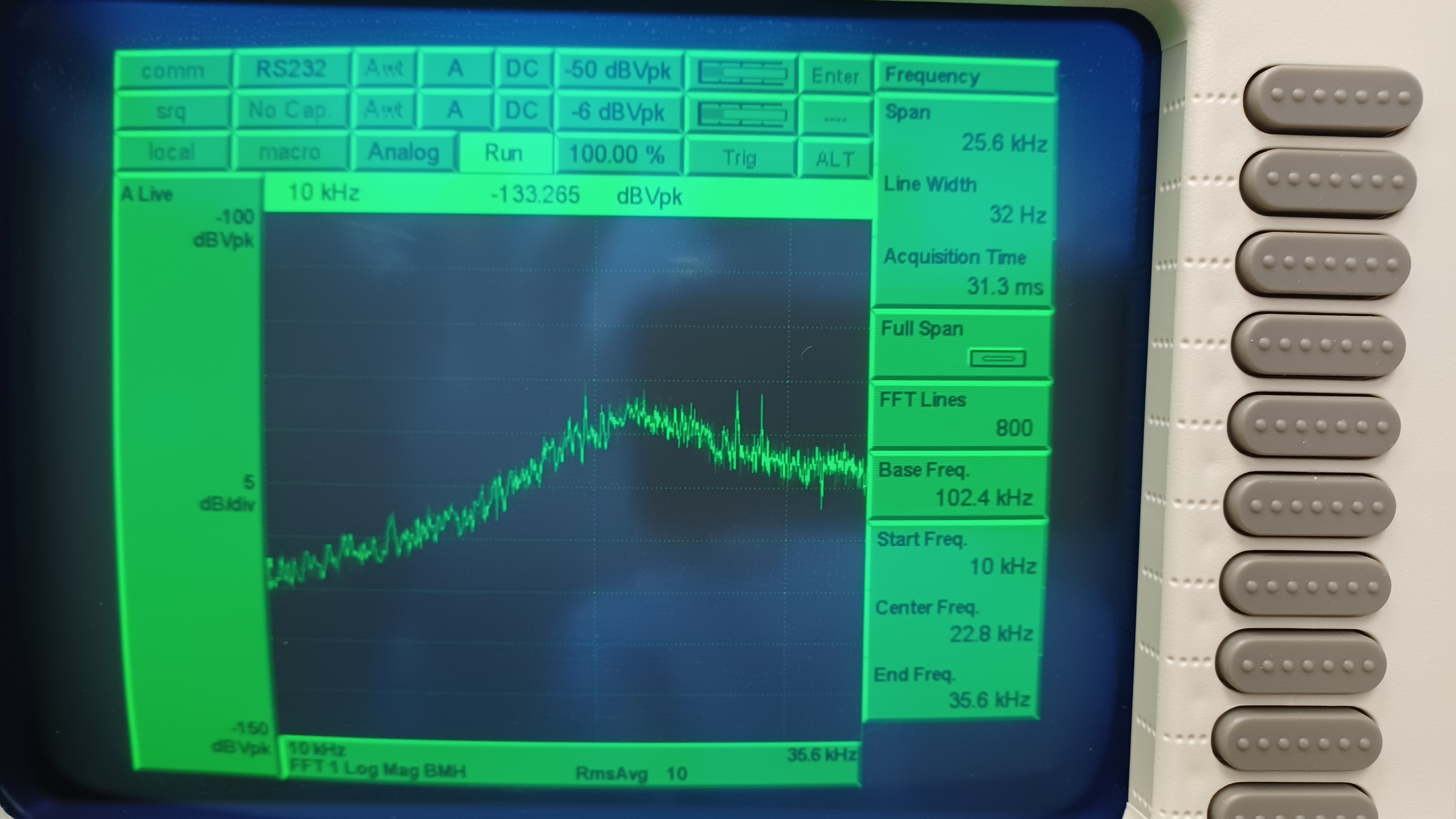
Good news though, the new notch at ~2.5MHz seems to have mostly squashed the 2.5MHz peak from the TTFSS IN1 spectrum; there was a little peak left over that we couldn't get rid of, an indication that the notch needs to be deeper. Since it looked like the notch worked, we decided to install it in the in-service box. Since it looked like we needed a deeper notch, we decided to use a 220µH inductor instead of the 120µH used in the spare TTFSS, paired with the same style 4.5pf-65pf adjustable capacitor. Marc did this (same way it was installed in the spare box, see alog linked above) and tuned the notch, then we installed the box and ran some measurements. The RefCav locked without issue, and without slamming 65V into the Pockels cell (got to about 5V, then settled down to around 2V with slider gains minimized). Before taking measurements, we returned the FSS slider gains to the values we've been using (14dB common gain, 11dB fast gain). First we looked at the IN1 spectrum, exact same measurement setup Jenne and Ryan used in December, and saw no evidence of the 2.5MHz peak (1st attachment). We then took a TF of TP7, which is the internal TTFSS test point immediately after the notch filters in the Pockels cell path, and saw all looked good there (2nd attachment); the 1st notch was found to be centered at 1.779MHz, and the 2nd centered at 2.5MHz. We then took an OLTF to check our UGF, and found it to be ~165kHz, a little more than half of our usual value of 400kHz. Odd. We increased the common gain to 22dB to get a UGF of ~400kHz (which gave us a phase margin of ~61°). We also took a look at the crossover (~25kHz), and found it to be OK with a FAST gain of 11dB. The 3rd attachment shows the OLTF as we left it, with a common gain of 22dB and a FAST gain of 11dB, and the 4th attachment shows the crossover (apologies for the blurriness on the 3rd attachment, it looked better on my phone while in the enclosure). This ended our work for the day. The common gain change was accepted in SDF. This closes LHO WP 10916.
Follow up SQZ measurements will tell us if the 2.5MHz peak is truly squashed or not (it looks like it on our end, at least).