JoeB (LLO), DriptaB, RickS
Yesterday, with Joe's guidance we populated the new MEDM screens he has generated such that we are now running the X/Y comparison in the front-end. See the O3 Pcal paper, LIGO-P2000113 for background regarding the X/Y comparison.
Dripta plans to append an aLog entry giving the details of the filter settings we implemeted yesterday.
Today, we used the data from last night's locked sections (at only ~20 Mpc range) to have a first look at the X/Y comparison.
One can calculate the X/Y calibration factor by hand using FFTs of the signals in both DARM and in the calibrated output of the receiver-side sensors at each end station.
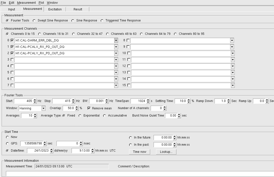
The settings for the DTT FFT measurement are shown in the first attachment.
The measured heights of the peaks in the spectra are:
DARM(410.2 Hz) = 7.94349e-11
DARM(410.3 Hz) = 7.97594e-11
PcalX Rx (410.2 Hz) = 5.45026e-12
PcalY Rx (410.3 Hz) = 5.47648e-12
The X/Y comparison factor (ideally unity), given by [PcalX(410.2) / DARM(410.2)] / [PcalY(410.3) / DARM(410.3)] = 0.99928. Differs from unity by 0.07% or 7 parts in 10,000. (good news)
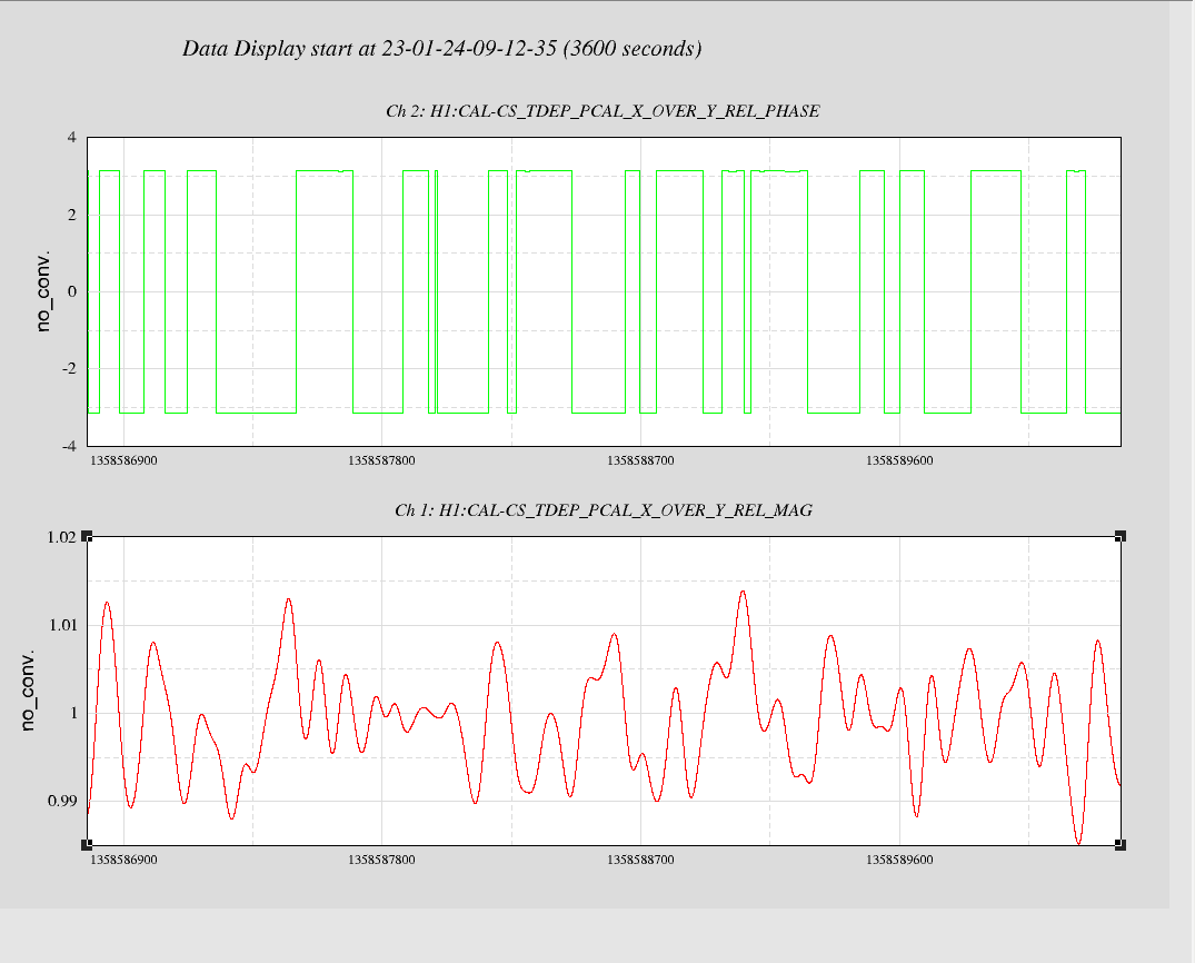
This X/Y Pcal calibration comparison factor, Chi_XY in the paper linked above, is continuously calculated by the front-end code. The second attached plot shows the results of the calculation during a one-hour period last night. This is our first look at the calculated data.
The filter settings used for the implementation of the Pcal X/Y comparison:
1. In the CAL_CS_PCAL_COMPARISON.adl ( SITEMAP > CAL CS > PCAL COMPARISON ) screen, we used the following settings:
- N AVERAGES: 10.000
- FFT LENGTH (sec): 60.000
2. From this screen, we get to CS_TDEP_PCAL_Y_COMPARE_PCAL screen ( PCAL Y COMPARE DEMOD > PCAL LINE DEMOD pulls up this screen ). We used the following settings:
- In OSCILLATOR block,
- f(Hz): 410.3 Hz
- SIN : 1.0
- COS: 1.0
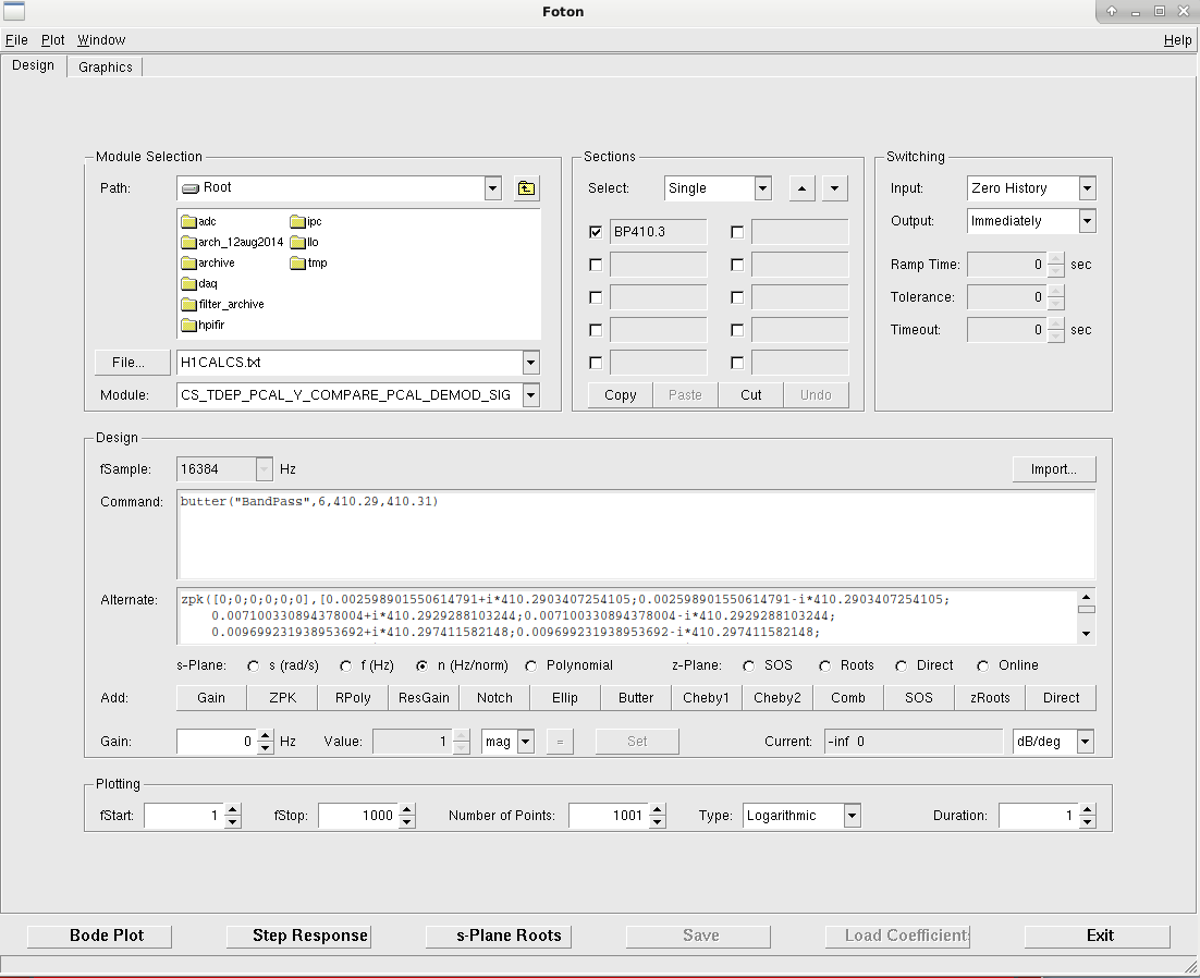
- Next, in H1CAL-CS_TDEP_PCAL_Y_COMPARE_PCAL_DEMOD_SIG (SIG button on SIGNAL block in the CS_TDEP_PCAL_Y_COMPARE_PCAL screen pulls up the filter bank) we put in a bandpass filter using the Foton settings as shown in the first attachment, PCALXYcompPCALYdemodsig.png
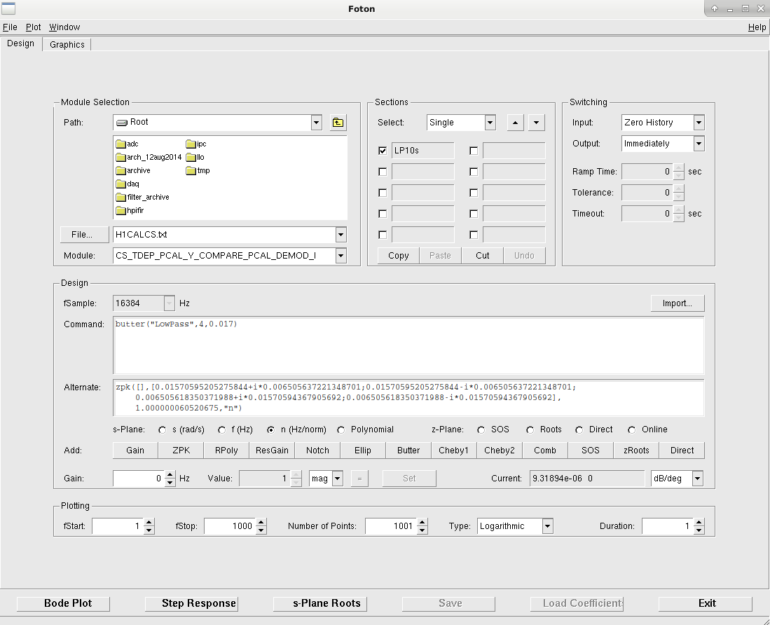
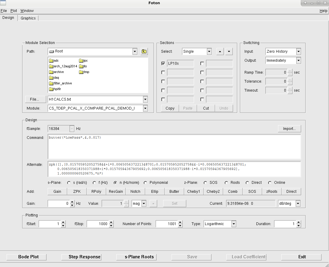
- In H1CAL-CS_TDEP_PCAL_Y_COMPARE_PCAL_DEMOD_I (I button on I block in the CS_TDEP_PCAL_Y_COMPARE_PCAL screen pulls up the filter bank), we put in a lowpass filter using the Foton settings as shown in the second attachment, PCALXYcompPCALYdemodI.png
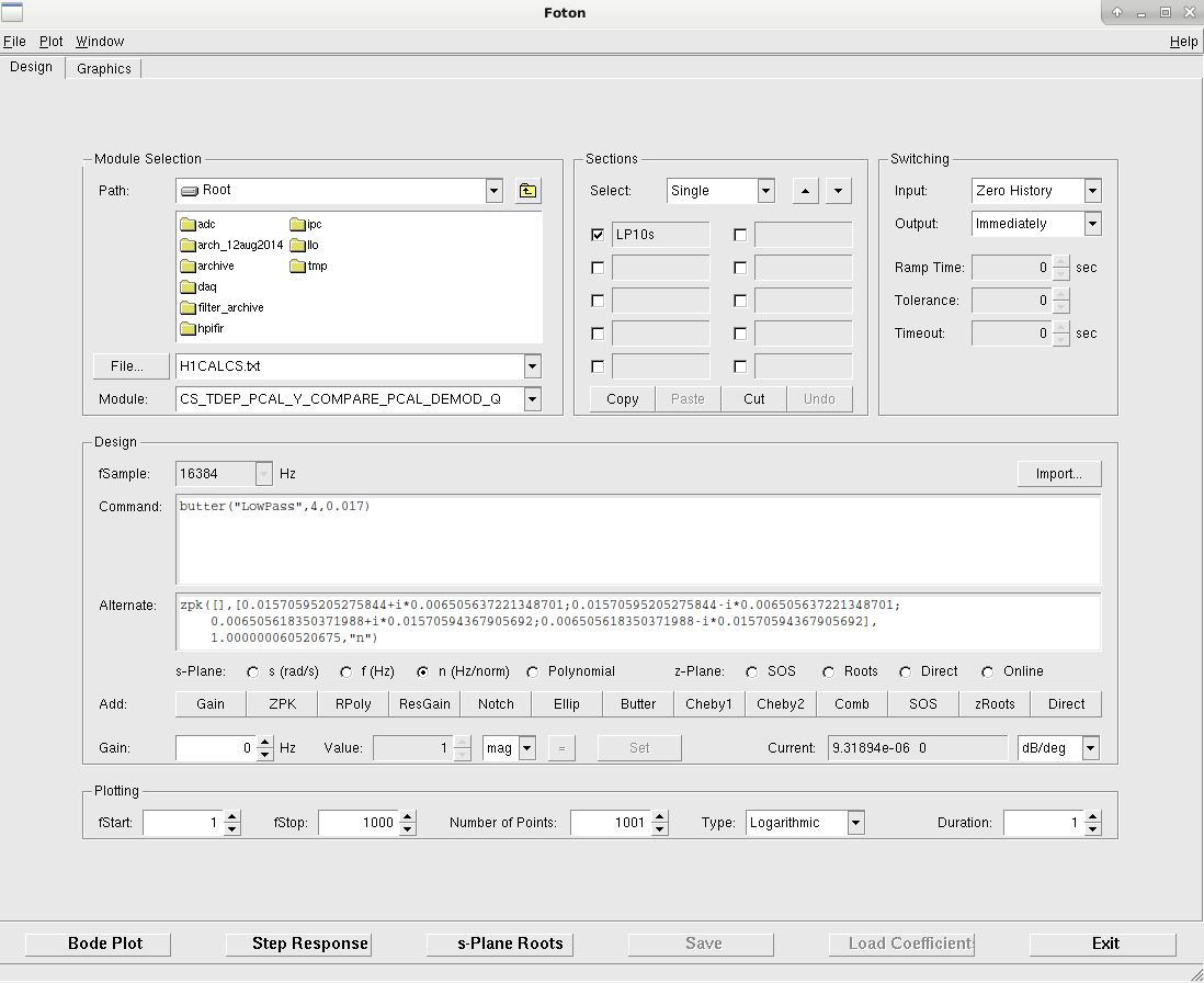
- In H1CAL-CS_TDEP_PCAL_Y_COMPARE_PCAL_DEMOD_Q (Q button on Q block in the CS_TDEP_PCAL_Y_COMPARE_PCAL screen pulls up the filter bank), we put in a similar lowpass filter using the Foton settings as shown in the third attachment, PCALXYcompPCALYdemodQ.png
3. We used similar settings at CS_TDEP_PCAL_Y_COMPARE_ERR screen ( PCAL Y COMPARE DEMOD > ERR DEMOD PCAL LINE pulls up this screen ).
- In OSCILLATOR block,
- f(Hz): 410.3 Hz
- SIN : 1.0
- COS: 1.0
- In H1CAL-CS_TDEP_PCAL_Y_COMPARE_PCAL_ERR_DEMOD_SIG (SIG button on SIGNAL block in the CS_TDEP_PCAL_Y_COMPARE_ERR screen pulls up the filter bank), we used the same foton settings as shown is PCALXYcompPCALYdemodsig.png to put in a bandpass filter with the only change in the "module" selected from the drop down menu being CS_TDEP_PCAL_Y_COMPARE_ERR_DEMOD_SIG.
- Similarly in H1CAL-CS_TDEP_PCAL_Y_COMPARE_PCAL_ERR_DEMOD_I (I button on I block in the CS_TDEP_PCAL_Y_COMPARE_ERR screen pulls up the filter bank), we used the same foton settings as shown is PCALXYcompPCALYdemodI.png to put in a lowpass filter with the only change in the "module" selected from the drop down menu being CS_TDEP_PCAL_Y_COMPARE_ERR_DEMOD_I.
- In H1CAL-CS_TDEP_PCAL_Y_COMPARE_PCAL_ERR_DEMOD_Q (Q button on Q block in the CS_TDEP_PCAL_Y_COMPARE_ERR screen pulls up the filter bank), we used the same foton settings as shown is PCALXYcompPCALYdemodQ.png to put in a lowpass filter with the only change in the "module" selected from the drop down menu being CS_TDEP_PCAL_Y_COMPARE_ERR_DEMOD_Q.
4. We did not make any changes/modifications to the CS_TDEP_PCAL_Y_COMPARE_EXT.
5. In the CS_TDEP_PCAL_X_COMPARE_PCAL screen, we used the following settings:
- In OSCILLATOR block,
- f(Hz): 410.2 Hz
- SIN : 1.0
- COS: 1.0
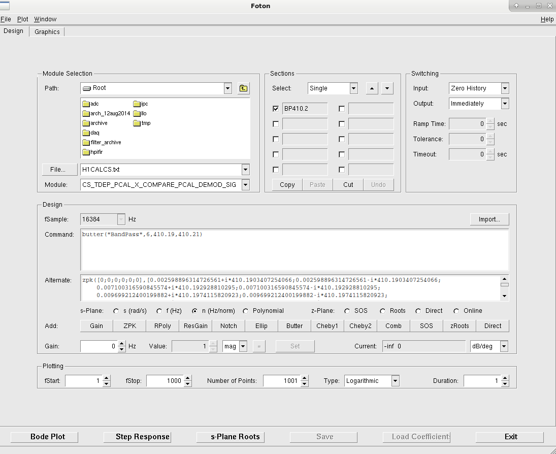
- Next, in H1CAL-CS_TDEP_PCAL_X_COMPARE_PCAL_DEMOD_SIG (SIG button on SIGNAL block in the CS_TDEP_PCAL_X_COMPARE_PCAL screen pulls up the filter bank) we put in a bandpass filter using similar Foton settings as shown in the fourth attachment, PCALXYcompPCALXdemodsig.png
- In H1CAL-CS_TDEP_PCAL_X_COMPARE_PCAL_DEMOD_I (I button on I block in the CS_TDEP_PCAL_X_COMPARE_PCAL screen pulls up the filter bank), we put in a lowpass filter using the Foton settings as shown in the fifth attachment, PCALXYcompPCALXdemodI.png
- In H1CAL-CS_TDEP_PCAL_X_COMPARE_PCAL_DEMOD_Q (Q button on Q block in the CS_TDEP_PCAL_X_COMPARE_PCAL screen pulls up the filter bank), we put in a lowpass filter using the Foton settings as shown in the fifth attachment, PCALXYcompPCALXdemodQ.png
6. We used similar settings at CS_TDEP_PCAL_X_COMPARE_ERR screen ( PCAL X COMPARE DEMOD > ERR DEMOD PCAL LINE pulls up this screen ).
- In OSCILLATOR block,
- f(Hz): 410.2 Hz
- SIN : 1.0
- COS: 1.0
- In H1CAL-CS_TDEP_PCAL_X_COMPARE_PCAL_ERR_DEMOD_SIG (SIG button on SIGNAL block in the CS_TDEP_PCAL_X_COMPARE_ERR screen pulls up the filter bank), we used the same foton settings as shown is PCALXYcompPCALXdemodsig.png to put in a bandpass filter with the only change in the "module" selected from the drop down menu being CS_TDEP_PCAL_X_COMPARE_ERR_DEMOD_SIG.
- Similarly in H1CAL-CS_TDEP_PCAL_X_COMPARE_PCAL_ERR_DEMOD_I (I button on I block in the CS_TDEP_PCAL_X_COMPARE_ERR screen pulls up the filter bank), we used the same foton settings as shown is PCALXYcompPCALXdemodI.png to put in a lowpass filter with the only change in the "module" selected from the drop down menu being CS_TDEP_PCAL_X_COMPARE_ERR_DEMOD_I.
- In H1CAL-CS_TDEP_PCAL_X_COMPARE_PCAL_ERR_DEMOD_Q (Q button on Q block in the CS_TDEP_PCAL_X_COMPARE_ERR screen pulls up the filter bank), we used the same foton settings as shown is PCALXYcompPCALXdemodQ.png to put in a lowpass filter with the only change in the "module" selected from the drop down menu being CS_TDEP_PCAL_X_COMPARE_ERR_DEMOD_Q.
7. We did not make any changes/modifications to the CS_TDEP_PCAL_X_COMPARE_EXT.
8. To load the coefficients in the filter bank, we went to H1CALCS_GDS_TP.adl screen (SITEMAP > CAL CS > H1CALCS GDS TP) and hit the COEFF LOAD BUTTON.