As part of the big OMC front-end upgrade we revamped the omcpi model to account for the fact that we are no longer undersampling.
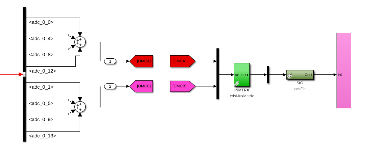
In the 512K IOP model this consists of (1st attachment):
- Each of the 4 ADC inputs of DCPD A and B are summed together.
- DCPD A and B channels are added using an input matrix (H1:OMC-PI_DOWNCONV_INMTRX)
- A filter module, H1:OMC-PI_DOWNCONV_SIG, is used to condition the data (at the moment it has the same compensation but not decimation filters as H1:OMC-DCPD_A0)
- The filter output is then down-converted, filtered and decimated at frequencies of n * 32.768kHz with n = 0, 1, ... 8, both I (cos) and Q (sin). The Q channels for n = 0 and 8 generated ouputs of all zeros, so they are omitted.
- These 16 outputs are then forwarded through IPC channels to the omcpi model.
The demdoulation is done with a lookup table that is synchronzied with GPS, so the demodulation phase is always 0 at 1PPS.
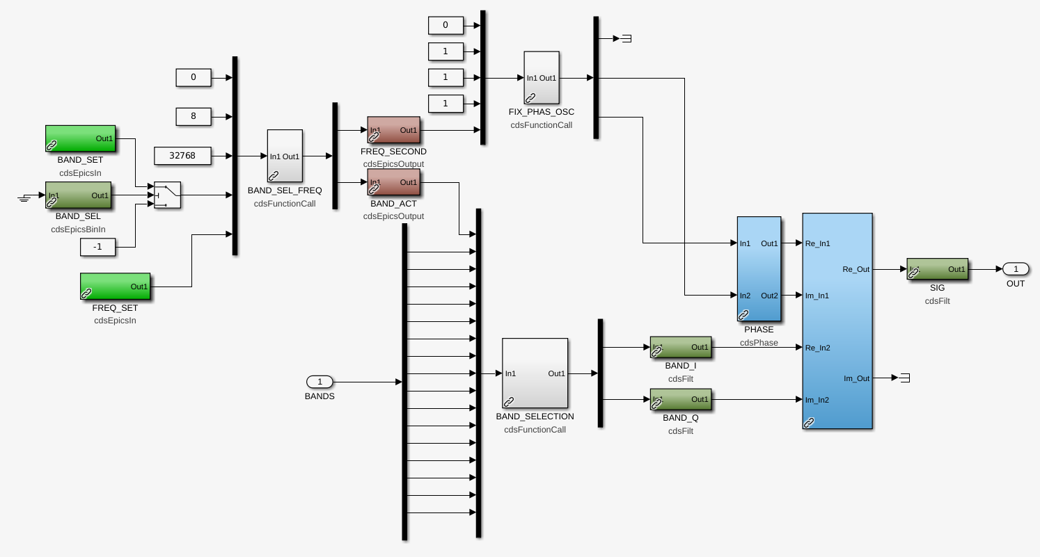
A second down-conversion is applied in the OMC PI model to get the PI modes into a a frequency band below 1kHz. The actual PI model (susprocpi) is still mostly the same and operates at 2048Hz. The second down-conversion is a 2 step process (2nd attachment):
- Depending on the frequency of the PI or more specifically the required offset frequency, the closest down-conversion band from the front-end is selected. The difference between the required offset frequency and the selected front-end down-conversion frequnecy is used as an input to an oscillator with a fixed phase relative to 1PPS.
- The cosine and sine outputs of this oscillator are then used to perform a second complex down-conversion using the selected IQ-band as the input. The final down-converted I channel is sent to a filter module and forwarded to the susprocpi model.
The susprocpi model uses a set of servo paths, each tailored for a specific PI mode, to compute the required feedback force, which then is sent to the corresponding PI model of a test mass (see alog 66188 for details).
The individual test mass pi models, susetmxpi, susetmypi, susitmxpi or susitmypi, also stayed more or less the same. The up-conversion is done with the original offset frequency using a fixed phase oscillator. The only difference is that we are using a cosine rather than the sine for the up-conversion to keep the same convention as in the down-conversion. The output is finally sent to an undersampled DAC, which actuates on the test mass.
The omc pi model also implements a set of BLRMS filters intended to monitor different sets of PI modes. These still exist but currently only use the lowest frequency band as an input. To monitor PI modes at frequencies above 32kHz this would have to be changed.
All the pieces are in place, but still neeed to be fully tested.