filiberto.clara@LIGO.ORG - posted 12:56, Tuesday 29 November 2022 - last comment - 13:35, Tuesday 28 February 2023(66078)
Installation of h1omc0 electronics
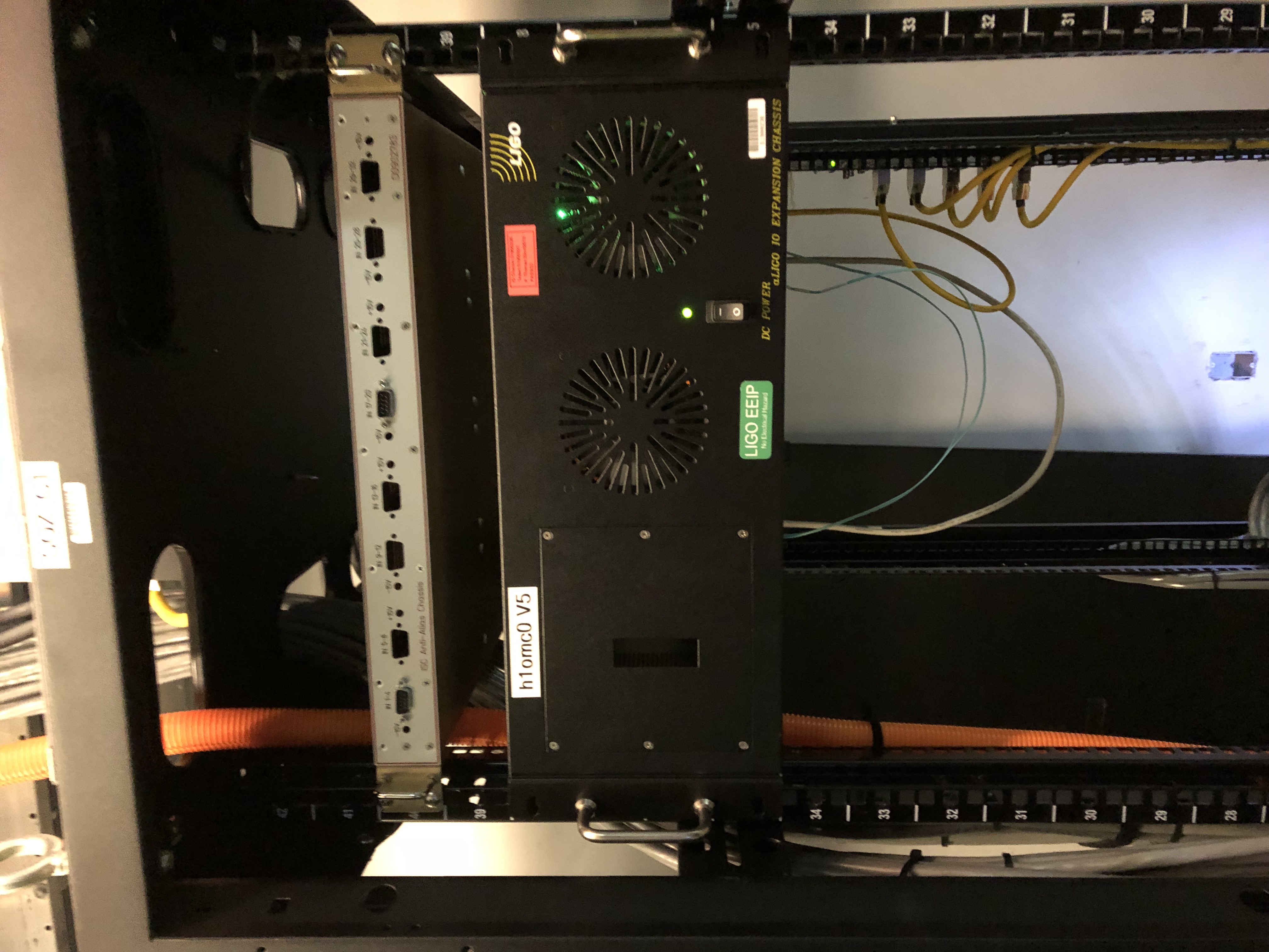
The following electronics were installed in the SQZ-C1 rack in the CER. Part of implementing a segregated OMC Front-End.
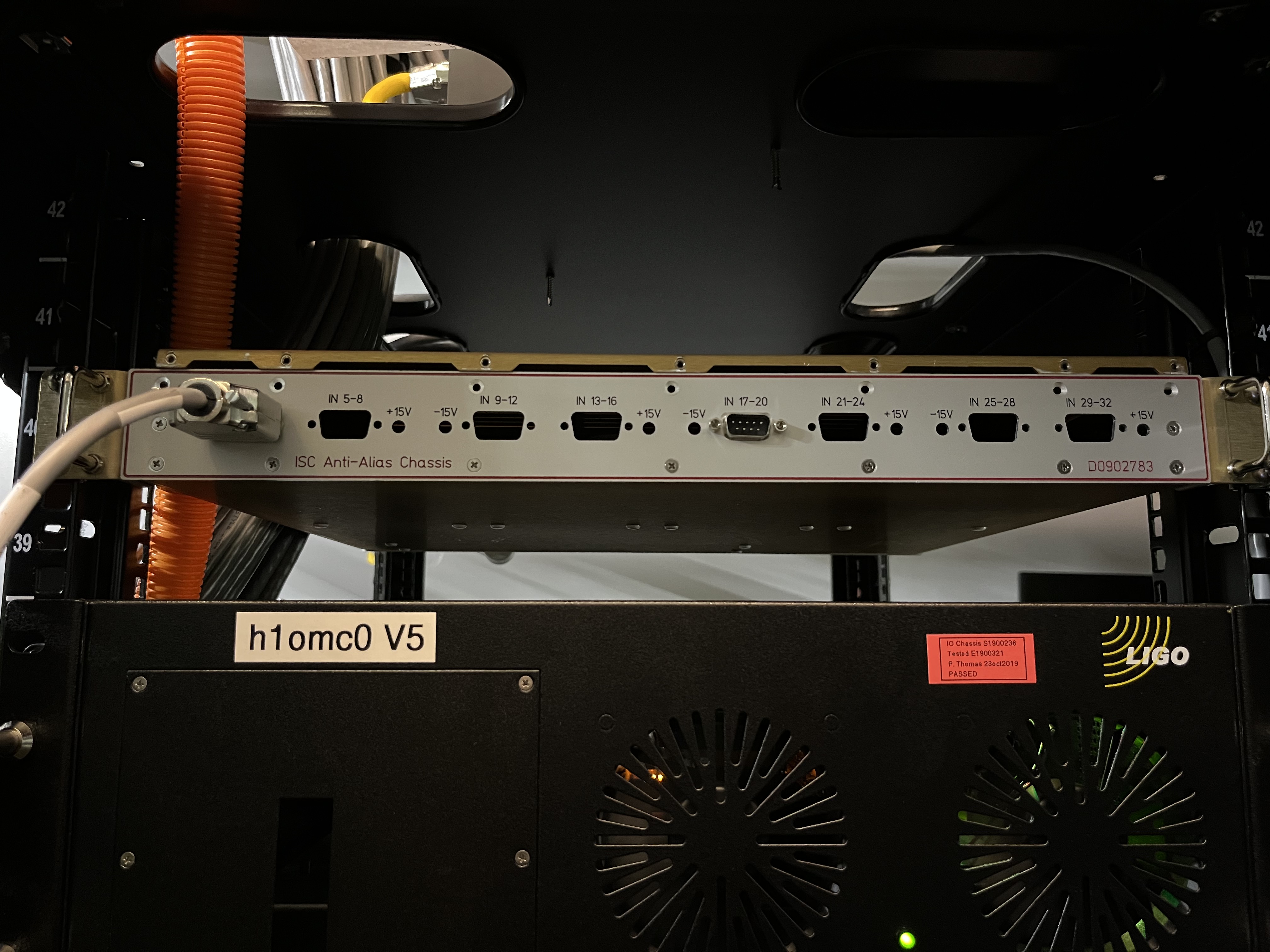
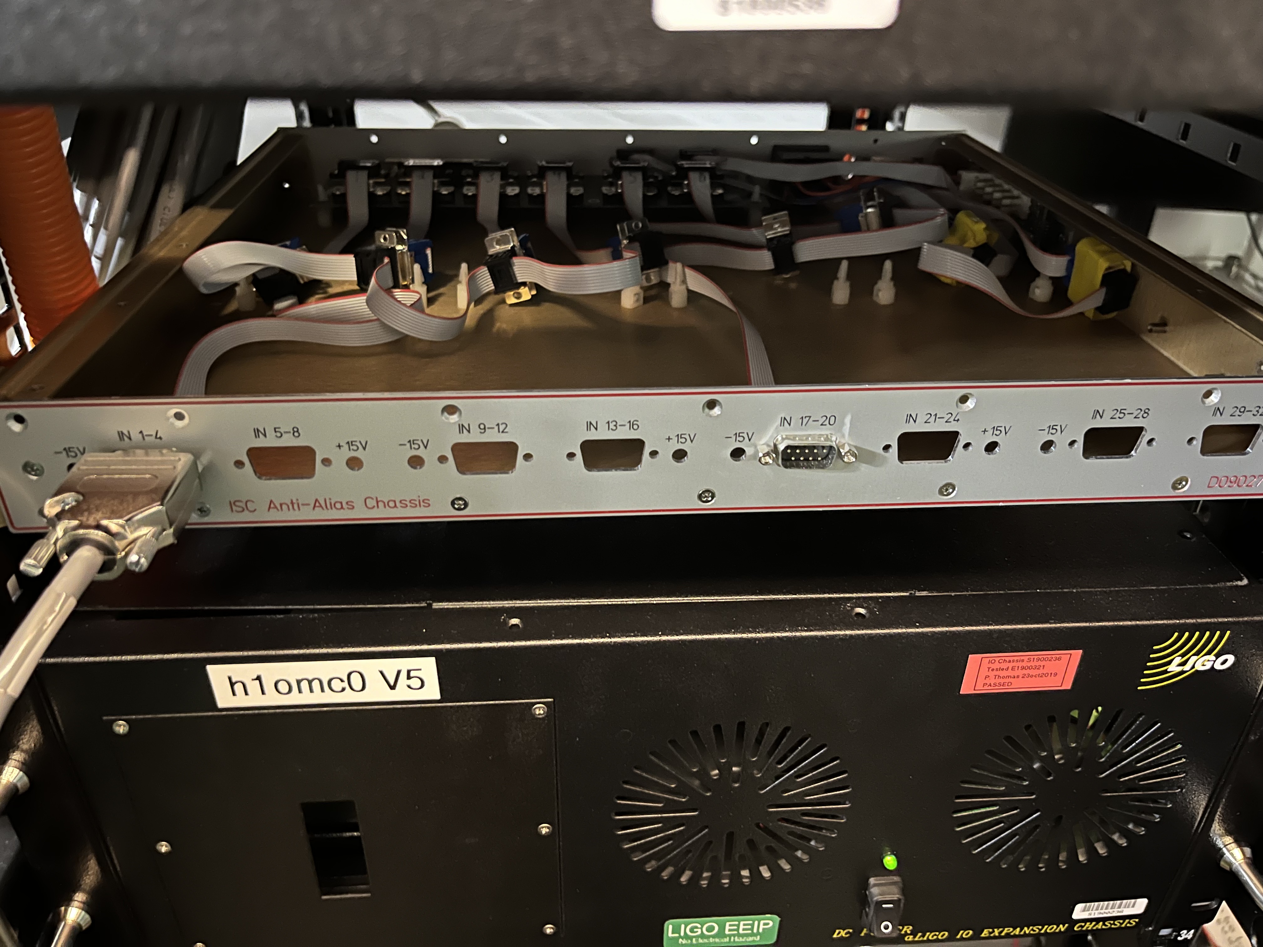
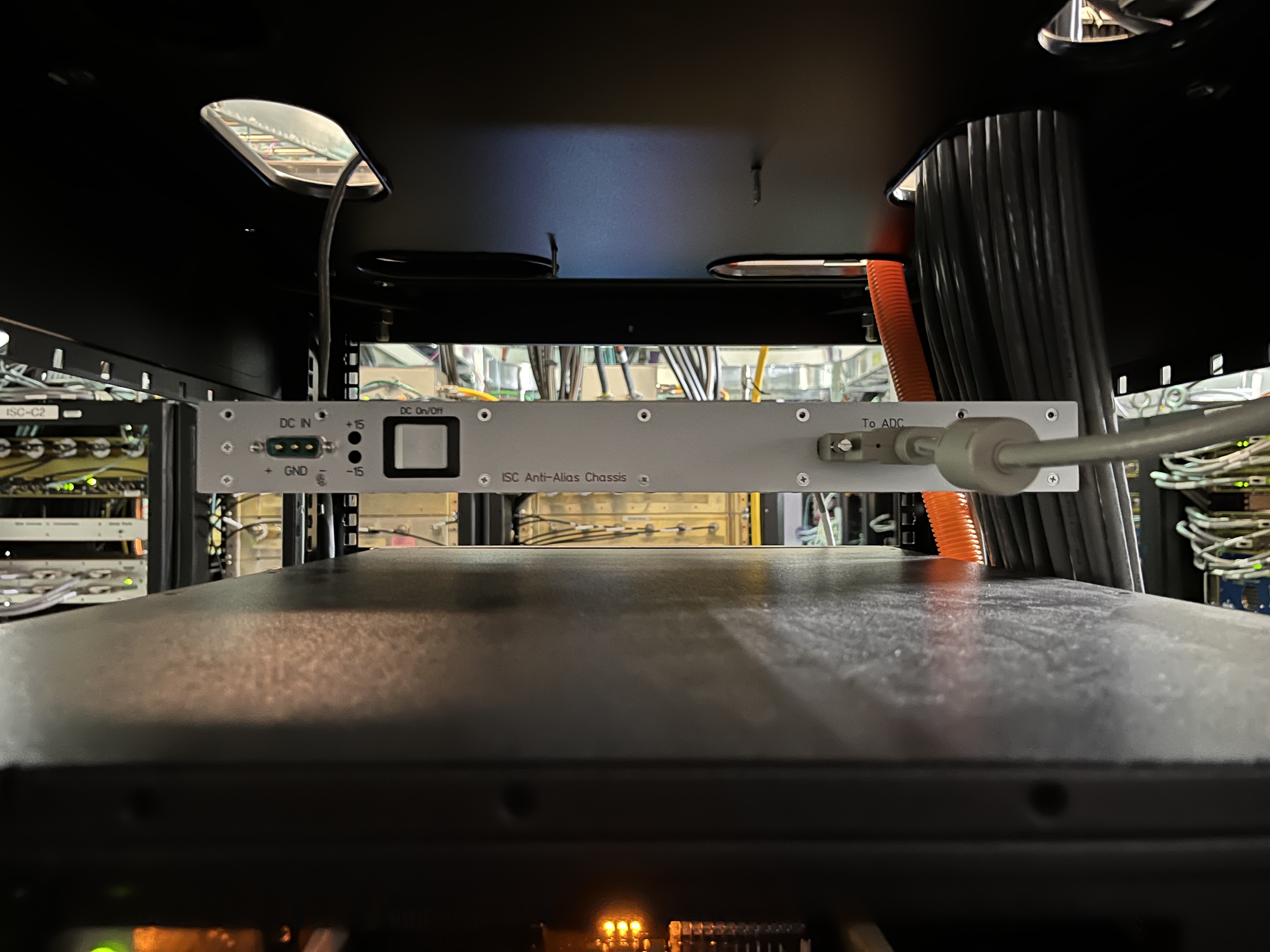
1. Modified AA D0902783 chassis (Slot U40)
2. h1omc0 IO Chassis V5 (Slot U35-38)
The IO chassis was upgraded to V5. A low noise ADC and adapter card are installed.
All AA boards in the AA chassis were removed. Chassis serves as a pass through.
A multimode fiber that connects the IO chassis and front end is patched from the CER to MSR (Patch panel ports 9-10).
Timing for the IO chassis is from the fanout chassis in the CER, port 1.
IO Chassis Serial Number: S1900236
D. Barker, F. Clara, E. Von Reis
Images attached to this report
Comments related to this report
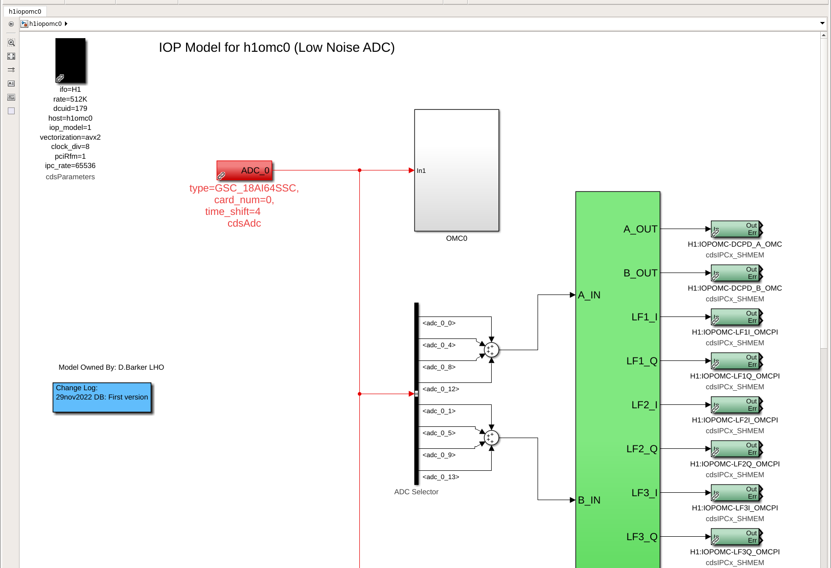
J. Kissel, F. Clara
D2300115
S2300016

Some more details on the AA chassis in case it sticks into O4 -- Fil made a quick redlined drawing of the D0902783 chassis assembly from which this "Pass through and copy 4x" AA chassis was "built" -- that's now both attached here as well as posted to the new drawing number listed above.

Also, although we haven't made a sticker yet for it, I reserved S2300016 as its serial number so we can keep track of changes, if any.
The attached pictures show the front, inside, and back of the chassis.

For the time being,
- DB9 input 1-4 is receiving (all respectively) the DCPD A and B output from the OMC Whitening chassis on channels 1 and 2, which are copied to ADC channels 0, 4, 8, and 12, and 1, 5, 9 and 13 and explicitly read out by the h1iopomc0 model as shown in the first attachment of LHO:66489. The remaining 2 channels on this DB9 are mapped into 2, 6, 10, 14 and 3, 7, 11 and 15, but there's no signal on them -- they're connected via the same long cable to pins 3-8 and 4-9 of the whitening chassis which are internally disconnected from each other, a.k.a floating (see J1 connector on page 1 of D2200044).

- DB9 input 17-20 is unloaded and open at the front of the chassis, but its signals internally are similarly mapped into ADC channels
    - CH17: 16, 20, 24, 28,
    - CH18: 17, 21, 25, 29,
    - CH19: 18, 22, 26, 30,
    - CH20: 19, 23, 27, (31 is overwritten by the ADC duotone signal).
There're no explicit test points in the h1iopomc0 front-end model for them.
As such, one should look at channels that come default from the RCG,
    H1:IOP-OMC0_MADC0_EPICS_CH${n}

where ${n} is the ADC channel number listed in the analog-to-digital channel map above.
Images attached to this comment
Non-image files attached to this comment

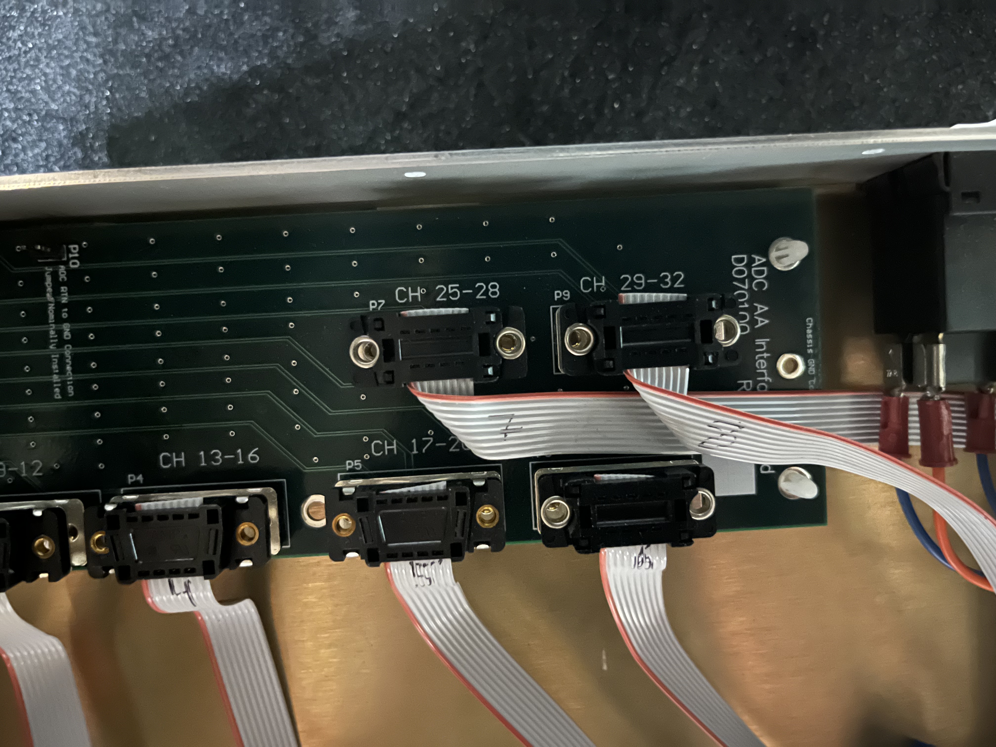
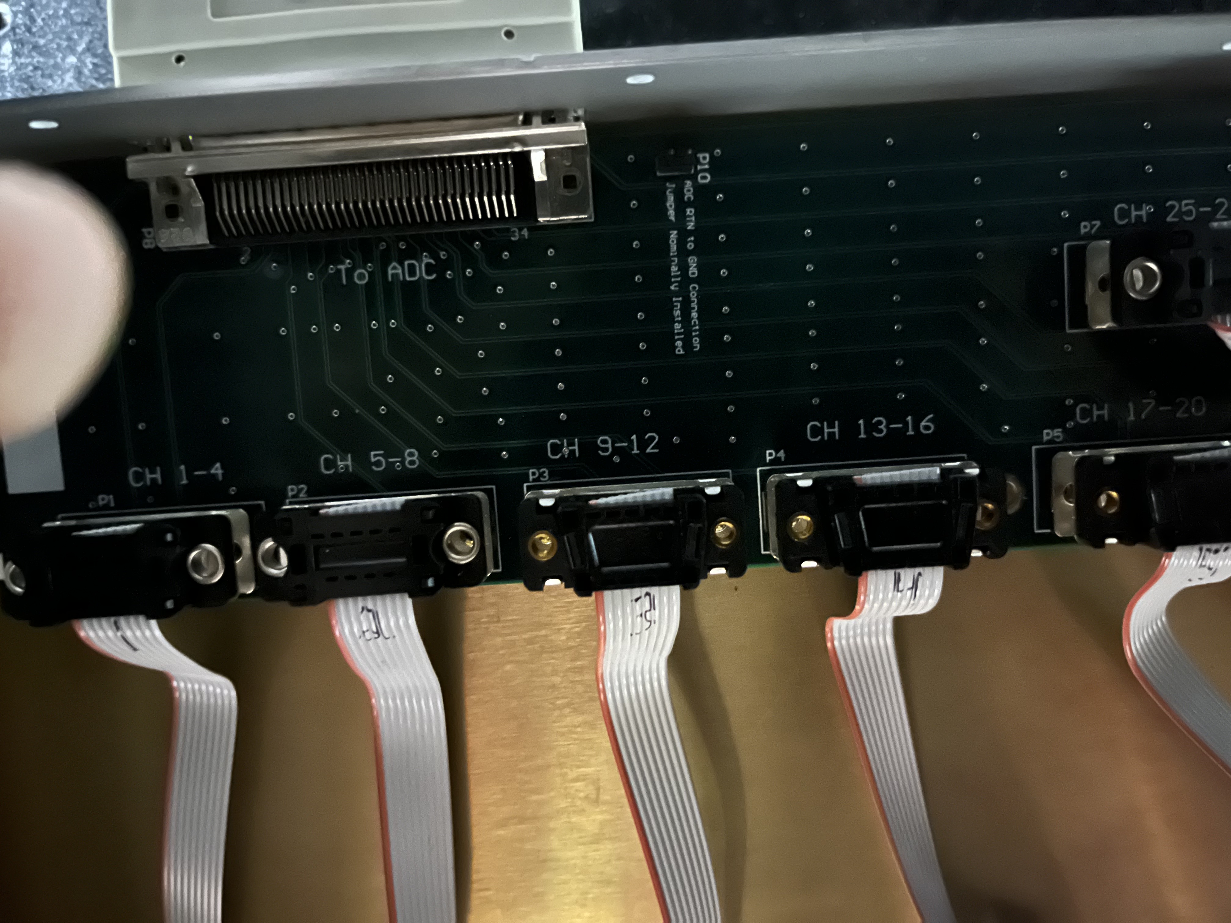
Here're some more photos of the inside of the chassis, zooming in for top-down views of the only card within the chassis, a D070100-v1 ADC AA Interface DB9 to SCSI board.

EDIT: Further investigations have determined that this is a -v1 of the D070100 board (a previous version of this log incorrectly suggested that S2300016 had a -v3). Later versions of the board clean up the electrical traces on the PCB in order to improve signal crossing.

I recommend we swap out the D070100-v1 board for a D070100-v3 board given that initial studies like LHO:67530 show clear, coherent, cross-coupling between channels.
Images attached to this comment