craig.cahillane@LIGO.ORG - posted 17:23, Friday 17 February 2023 - last comment - 17:40, Friday 17 February 2023(67488)
CHARD Pitch OLG at 60W
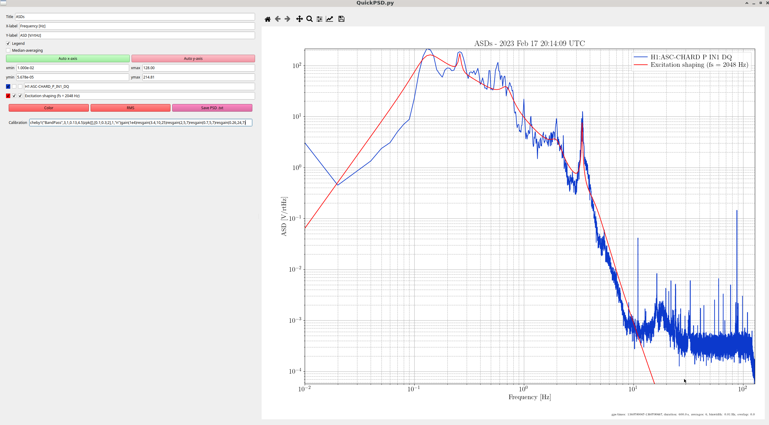
Earlier in the lock today, I tuned an injection for CHARD pitch OLG (PNG 1).

OLG
Looking at the 0.01 Hz binwidth plot, there are six UGFs in the CHARD P OLG:
0.35 Hz
0.47 Hz
1.0 Hz
1.2 Hz
2.3 Hz
3.2 Hz

The second two pairs of UGFs are due to suspension resonances.
There are rapid phase changes around those peaks, and zeros in the phase nearby prevent us from raising the gain here.

The first UGF is necessary, but the second at 0.47 Hz seems to be marginal and self-inflicted.  I do believe this effect is real, although it's not showing up in the models.
We could
1) reduce the gain in the whole loop, or
2) try to slightly reduce gain and gain phase at 0.47 Hz.


Digital Filters
In contrast to some of the other RPC we've seen at 60W, the CHARD P radiation pressure compensation is doing a great deal here (see last PDF).
Unlike with CHARD Y where there was an unintended dip at 0.7 Hz, these controllers do not cancel each other out anywhere at 60W (except at around 23 Hz, which is far above the loop bandwidth).
Overall, this digital filter design looks healthy at this power.
If this RPC gain were to increase by a factor of around 3, I would double check the behavior at 5 Hz is not cancelling.


I was not able to attach the .txt for the 0.01 Hz binwidth (I think the file was too big), but it lives at
/ligo/gitcommon/noise_recorder/data/chard_pitch_injection/20230217/unbiased_olg_H1_ASC_CHARD_P_A_EXC_gps_start_1360701471_binwidth_0p01.txt
Images attached to this report
Non-image files attached to this report


Comments related to this report
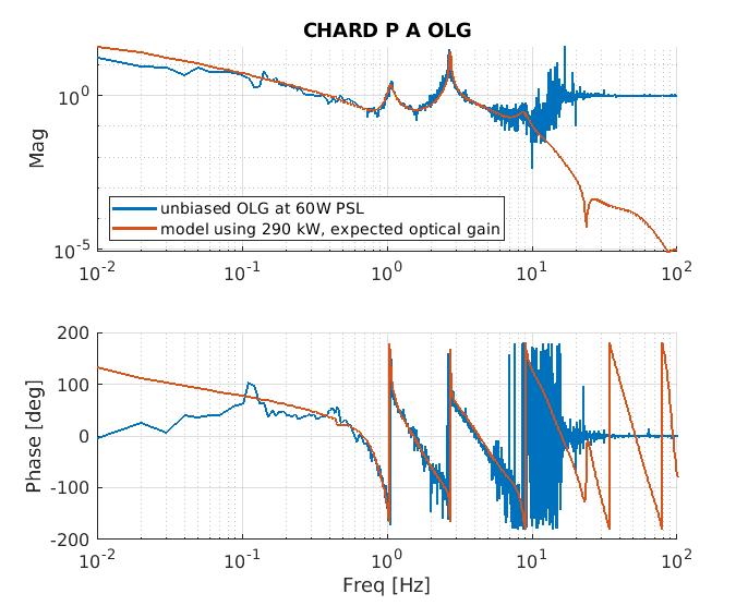
I have updated my model to model the OLG at the "A" point (previously I modeled the open loop gain in parallel with the RPC path). I have attached my olg model for CHARD P A overlaid with Craig's measurement.
Model details:
- this model uses the L2 to L3 and L3 to L3 free suspension transfer functions of the test masses, as modeled by Brett Shapiro. I confirmed the modeled TF accuracy by measured the suspension transfer function myself.
- This model does not account for the M0 portion of the loop, as that will take effect at very low frequency (there is an integrator in the top mass locking filters)
- This model uses the updated optical gain I measured last Friday after rephasing the REFL WFS and correcting the seg4 gain of REFL A. I corrected the measured optical gain at 2W to the optical gain we expect at 60W after reducing modulation depths: 1.78 e10 ct/radian (3.317e10 ct/rad at 2W)
- This model applies the current digital control and radiation pressure compensation
- This model uses 290 kW of circulating power, which I determined by plotting several different arm powers and attempting to match Craig's measurement
I have also attached the .mat file containing the frequency, magnitude, and phase of the model from 0.01 Hz to 100 Hz for those who might like to plot it themselves.
Images attached to this comment
Non-image files attached to this comment
