jeffrey.kissel@LIGO.ORG - posted 16:59, Friday 03 March 2023 (67760)
Remote, DAC Driven Test of OMC DCPD Sensing Chain with TIA and Whitening BYPASSED
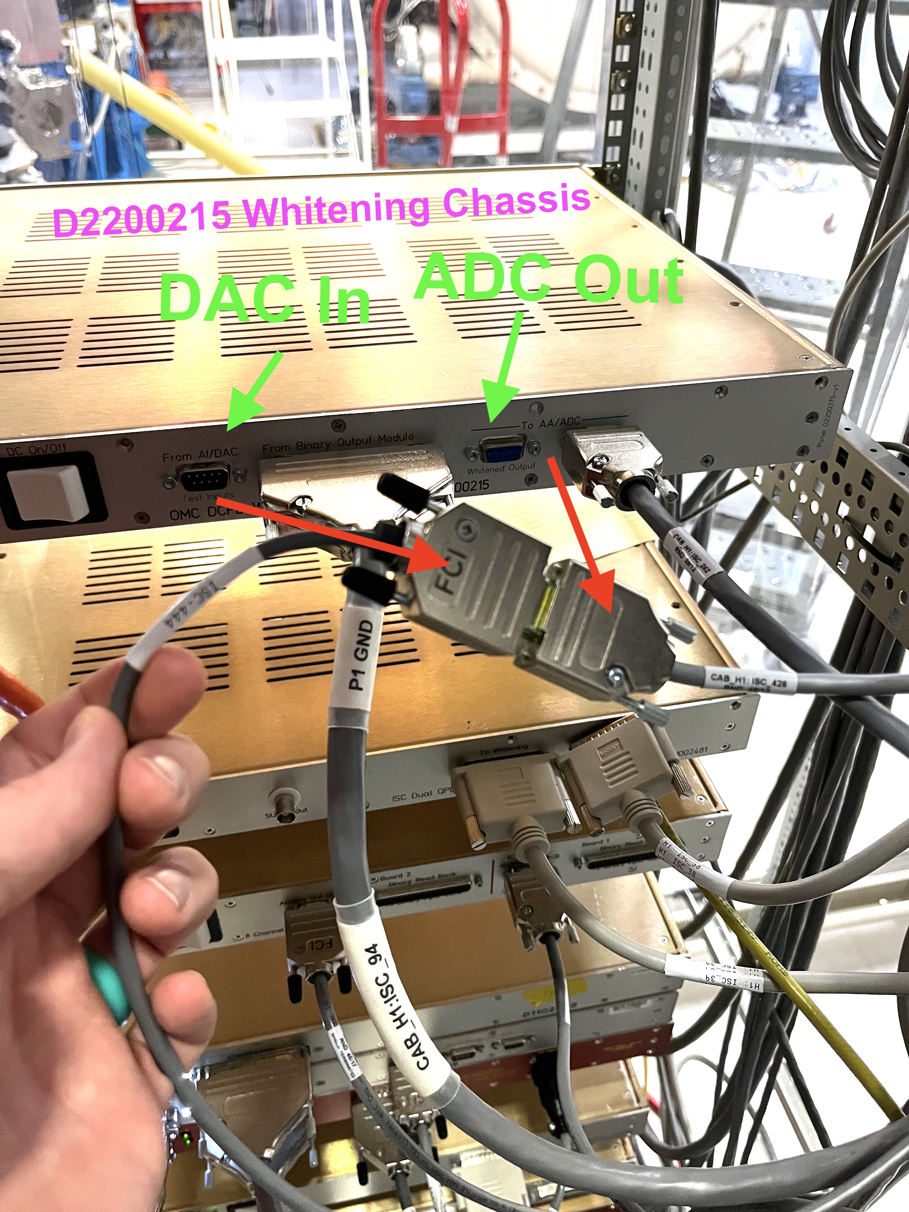
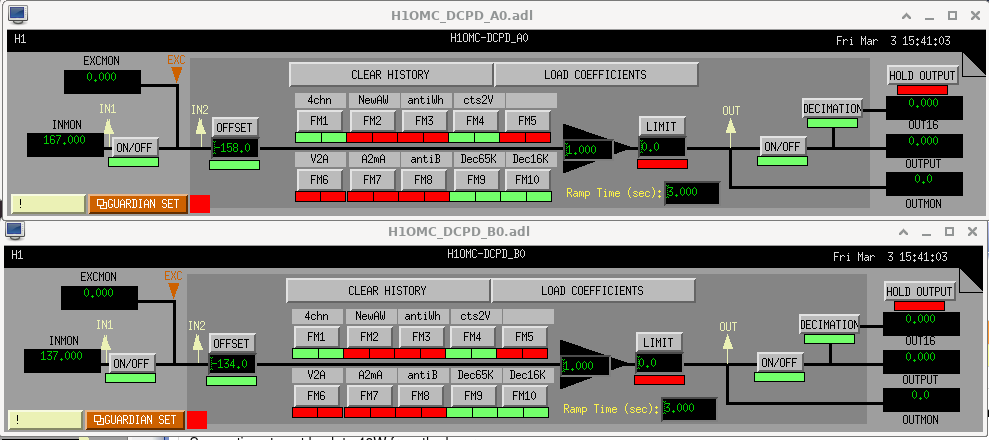
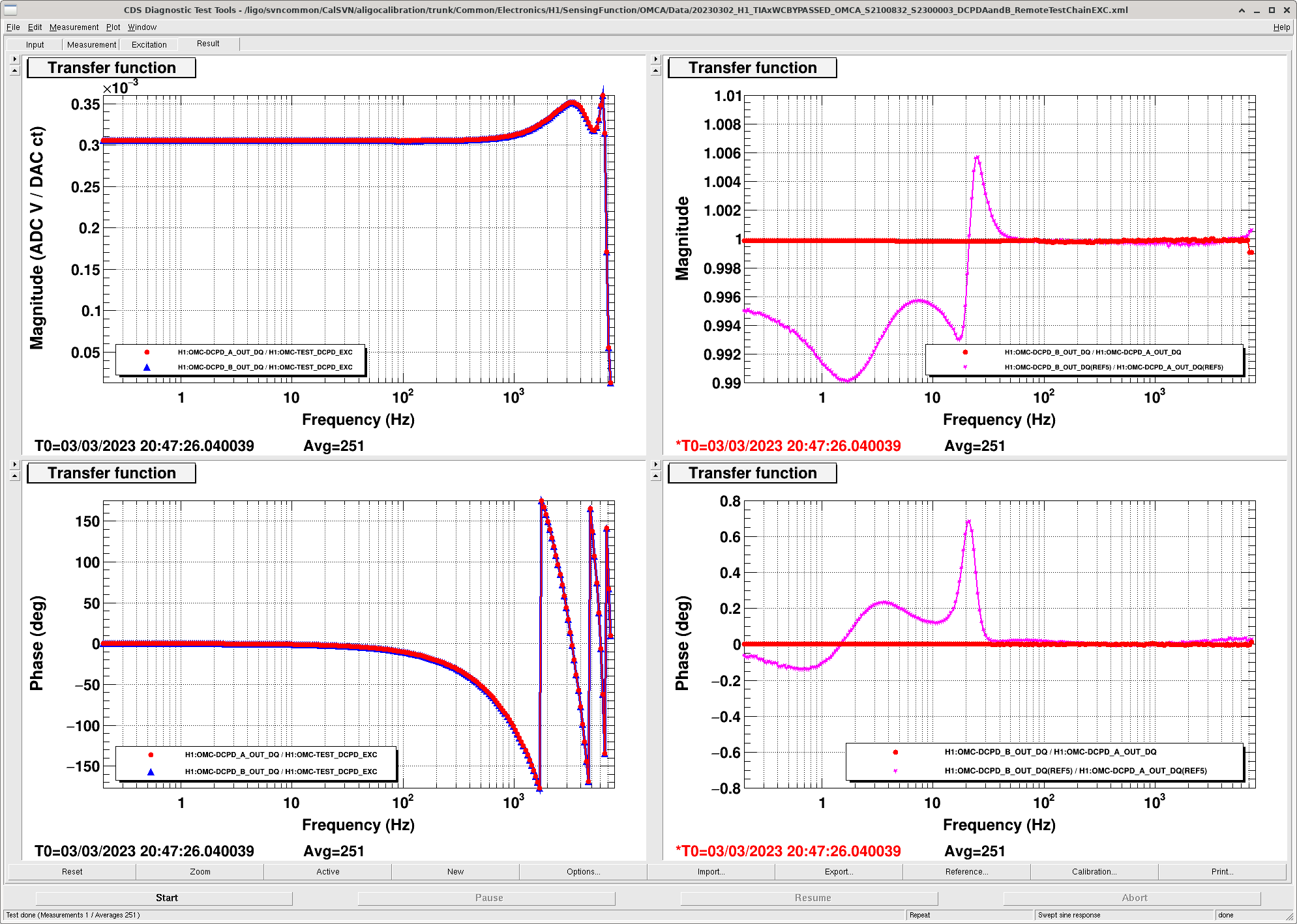
J. Kissel, (witnessed by H-Y Huang & B. Weaver)

We're continuing to try to validate the high-frequency portion of our pyDARM parameter set in different ways, in hopes to keep up with and model all the changes that have been happening to the OMC DCPD Sensing Chain.

Yesterday (LHO:67730), we re-did the OMC full remote test signal chain of the OMC DCPD sensing path since it hadn't been done in a while.
While we saw a change in the low-frequency (< 100 Hz) end of the measurement, we attributed that change to the OMC DCPD's transimpedance amplifier (TIA).

Today, I wanted to isolate the portion of the signal chain that really only has high frequency response that we saw change as well. So I created a "loop back" measurement, where I drove the 524 kHz ADC system directly with the DAC -- a measurement that's strikingly simple now that we're using the D2200215-style whitening chassis. Namely,
    - The DAC input drive is copied onto on pins 1-6 and 2-7 of a DB9 with the cable "ISC_444". This normally goes through the whitening chassis as a passthrough to the test input of the in-vac TIA, then through the TIA response itself, then through the whitening filter within) before hitting the ADC cable on its way out to be digitized. The end of ISC_444 that connects to the whitening chassis is a "sockets" connector.
    - The OMC DCPD A and B signals come out on cable "ISC_426" as they come out after whitening ... on pins 1-6 and 2-7. The end of ISC_426 that connects to the whitening chassis is a "pins" connector. Convenient!
I unplug the two cables from the whitening chassis, and connect them together, and bingo, bango, et. voila, I have a loop back measurement that isn't confused by the response of either the TIA or the Whitening.

See first attachment, which shows a picture of this setup.

In doing so, I also turned off the compensation for the TIA and whitening in the A0 / B0 banks, since they're bypassed in analog and don't need to be compensated in this measurement.

The second attachment shows a screencap of the OMC-DCPD_A0 and OMC-DCPD_B0 banks during this measurement.

The third attachment shows the results. The left two panels show the magnitude and phase of the H1:OMC-DCPD_[A,B]_OUT_DQ / H1:OMC-TEST_DCPD_EXC transfer functions. The right two panels show magnitude and phase of the transfer function OMC-DCPD_A_OUT_DQ / OMC-DCPD_B_OUT_DQ, i.e. the ratio of the two paths.

For the left two panels, Unlike the units and scale of full test loop as it's normally connected (see description on LHO:62653) *this* special configuration of the transfer function, between the same digital channels, EXC: H1:OMC-TEST_DCPD_EXC RESP: H1:OMC-DCPD_[A,B]_OUT_DQ, i.e.
    H1:OMC-DCPD_[A,B]_OUT_DQ / H1:OMC-TEST_DCPD_EXC
now has units of [ADC V / DAC ct], since the measurement includes only
    [ ] The digital AI filter which converts the digital drive from 16 kHz to 65 kHz, which has unity gain at DC, and plenty of phase-loss and magnitude response,
    [-] The 16-bit 65 kHz DAC gain for the digital drive excitation,
    [ ] The analog 65 kHz to analog AI filter which has (almost) unity gain, and some phase loss impact below 7 kHz, but otherwise "invisible" in magnitude,
    [ ] The now direct connection between AI output and AA input,
    [-] The 4 copies of the signals that are created within the "copy and pass-through" analog AA filter which has (almost) unity gain and no frequency response,
    [-] The 18-bit 524 kHz ADC gain of the analog voltage coming in from the analog AA,
    [-] The digital sum of the 4 channels, then a digital "4chn" divide by 4, to get the sum signal back into single-channel units as though it were a single ADC channel
    [-] The "cts2V" compensation (inversion) of the 18-bit 524 kHz ADC gain, to get back into ADC input voltage
    [ ] digital AA filter which converts the digital drive from 524 kHz to 65 kHz "Dec65k" filter, which has unity gain, and some phase loss impact below 7 kHz, but otherwise "invisible" in magnitude,
    [ ] digital AA filter which converts the digital drive from 65 kHz to 16 kHz "Dec16k" filter, which has unity gain at DC, and plenty of phase-loss and magnitude response

and thus we expect a DC gain of
    [ ] 1                        [LSC DAC ct / IOP DAC ct]
    [-] 20 / 2^16 = 3.052e-4     [DAC V_DIFF / DAC ct]
    [ ] ~1                       [AI V_DIFF / DAC V_DIFF]
    [ ] 1                        [AA IN V_DIFF / AI V_DIFF]
    [-] 4                        [AA OUT V_DIFF / AA IN V_DIFF]       # four copies
    [-] 2^18 / 40 = 1.525e-4     [IOP ADC ct / AA V_DIFF]
    [-] 0.25                     [A0 FM1 OUT ct / IOP ADC ct]         # "4chn"
    [-] 40 / 2^18 = 6553.6       [A0 FM4 OUT "V" / A0 FM1 OUT ct]     # "cts2V"
    [ ] ~1                       [A0 FM9 OUT "V" / A0 FM4 OUT "V"]    # Dec65k
    [ ] ~1                       [A0 FM10 OUT "V" / A0 FM9 OUT "V"]   # Dec16k
    = (20 / 2^16) * 4 * (2^18/40) * (0.25) * (40/2^18)
    = 20 / 2^16
    = 3.052e-4 [ADC V / DAC ct]

and this is indeed what we see, including the high frequency response that's dominated by the two digital 16k to 65k filters (one an AI, the other an AA) in magnitude, and a bunch of phase loss from those digital AAs, the analog AI, the digital 524 kHz AA, and several computational delays.

Also, on the right two panels, we see that the ratio of these two signal paths is somewhere between 1.0000 and 0.9998 across the entire frequency band -- *very* well matched. So all of the imbalance that we saw in yesterday's measurement must be from the TIA and Whitening Chassis (shown in pink for reference).

Hsiang-yu will take this data and use it to further validate our pyDARM model of this more simple system (i.e. one that's not confused by the poor compensation of the time-dependent TIA response).

The data taken during this measurement has been saved to tha CalSVN here:
/ligo/svncommon/CalSVN/aligocalibration/trunk/Common/Electronics/H1/SensingFunction/OMCA/Data/
    20230303_H1_TIAxWCBYPASSED_OMCA_S2100832_S2300003_DCPDAandB_RemoteTestChainEXC.xml
    20230303_H1_TIAxWCBYPASSED_OMCA_S2100832_S2300003_DCPDAandB_RemoteTestChainEXC_tf.txt
where the export, *_tf.txt has columns [freq, real(A), imag(A), real(B), imag(B)].
Images attached to this report