H. Y. Huang, J. Kissel
J. Kissel took measurement without TIA and whitening in sensing at 03 March. (LHO:67760)
To model this by pyDARM, I assume the compensation filter in pyDARM is *good*, so I only remove the uncompensation part. For example, TIA uncompensate pole in 11.08 and 10.220 kHz. Uncompensate whitening filter pole in 44500.68 Hz. Due to removal of V2A and mA2A filter in Foton, I divide the remaining components by 1e-2 to account for this change in model. The used IN file and the script are stored at the link.
The attachment:
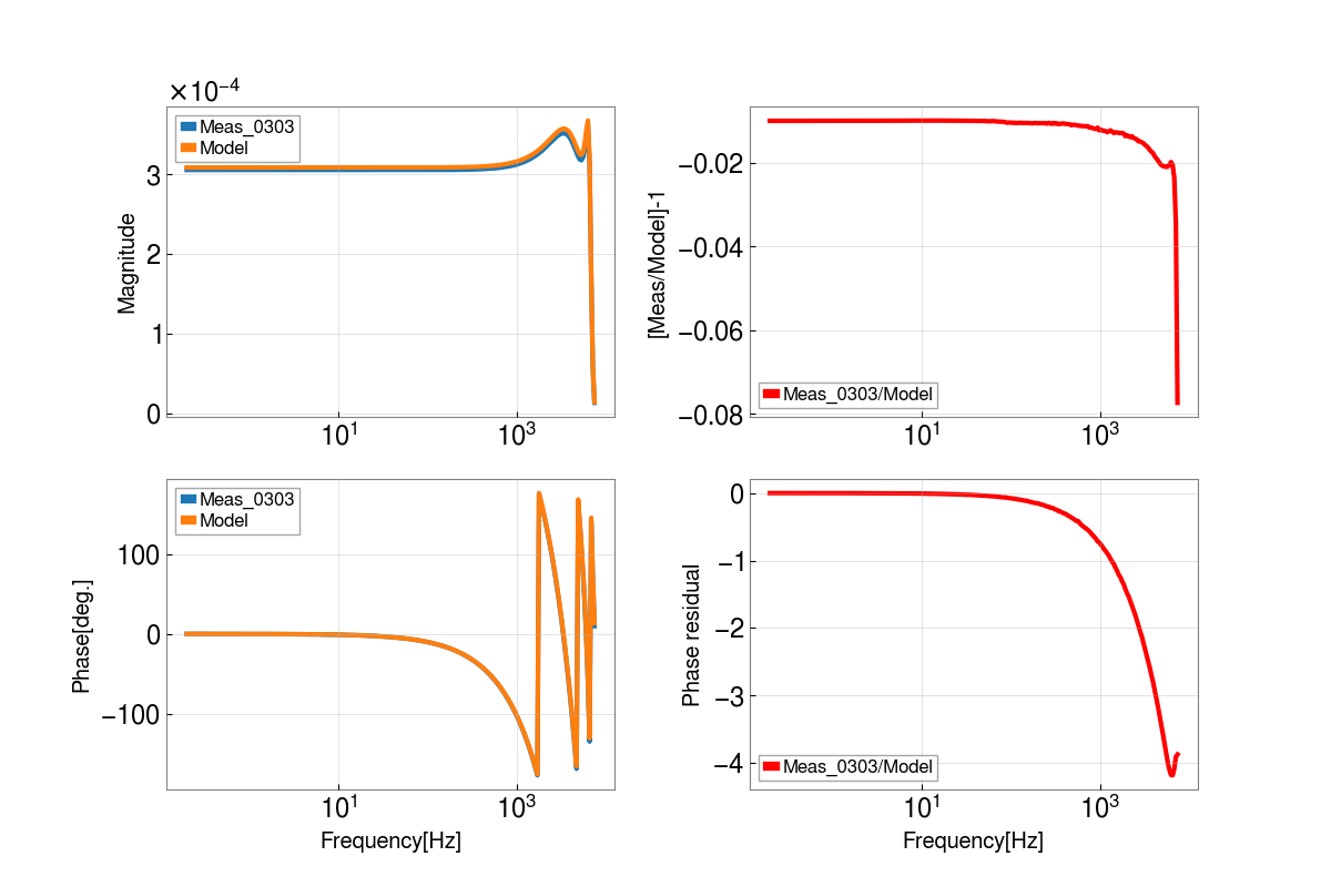
Figure 1: The quadplot for model and measurment. Compare to prevoius one (LHO:67765), the slope below 10 Hz and the peak of TIA complex pole pairs around 15~20 Hz are removed. The residual in magnitude below 1 kHz is close to 1% and the phase loss in 1 kHz is 1 degree. The magnitude and phase residual in higher frequency still have some differences.
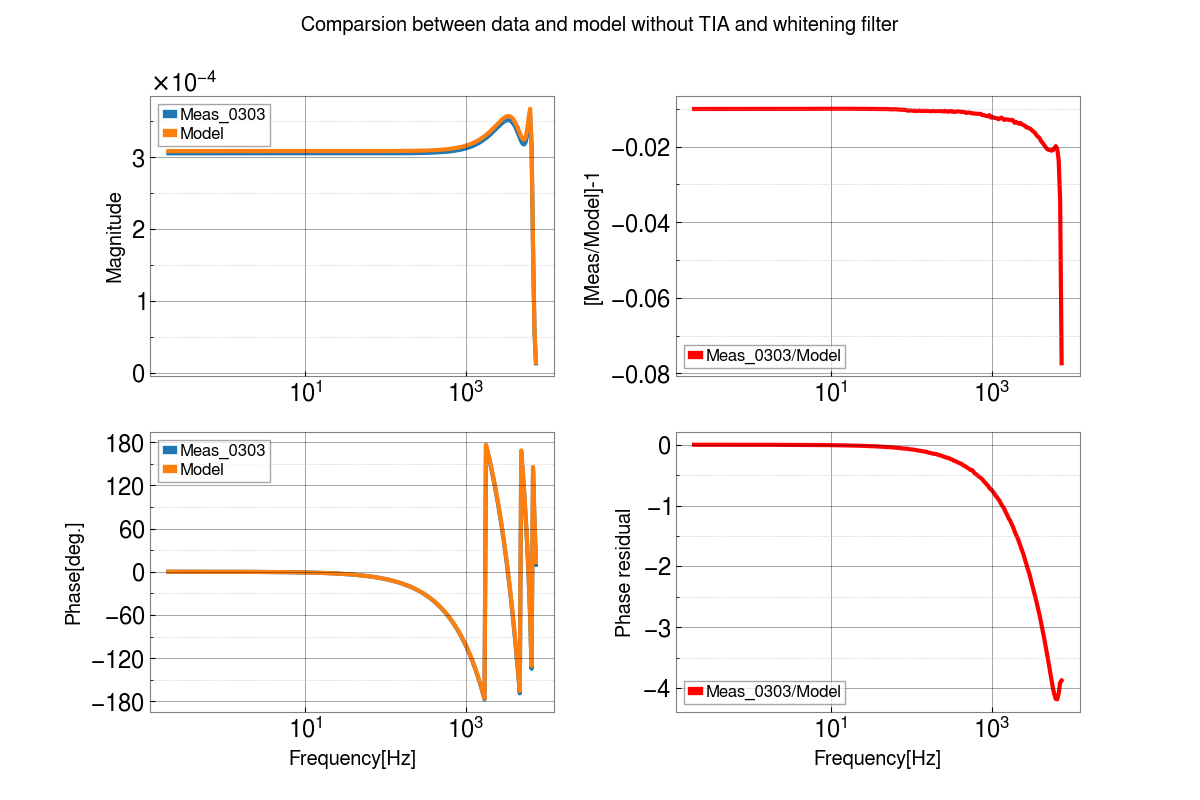
Figure 2: This quadplot follows the above Figure 1. In addition, the 2 us time delay(TD) is added shown as Blue line to investiagate extra, necessary time delay that fits the phase trend of measurement.

Hsiang-Yu Huang
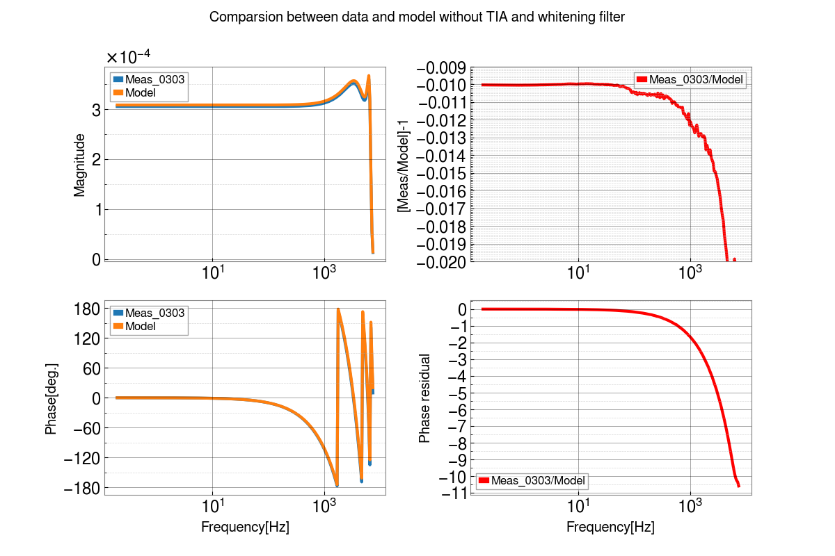
Add major and minor tickers for y-axis in attached figure.
Hsiang-Yu Huang
Add more accurate tickers in magntidue residual part. At the same time, remove TIA apparent delay because of high frequency poles by settting to 0.
I also save the magitude residual with corresponding freqeuncy vector from 0.2 Hz to 37 Hz. Filename is freq_magres.txt and stored in this link.
The used INI file for pyDARM is also stored in the same place.
After conversing with Hsiang-yu, and reviewing his code and the pyDARM code carefully --  I think I now understand his statements and modeling a bit better so I rephrase them here, and try to navigate through the pyDARM universe pulling out all the relevant hoops that one has to jump through. In the end, I have a few suggestions of things we can try that I think are the remaining outstanding issues that might explain why there's still a residual that has an overall gain discrepancy of meas/model - 1 = 0.01 (or meas/model = 0.99), and disagreement with the response at high frequency.

Hsiang-yu points to a script that creates the model of the BYPASSED measurement, which lives on the LHO cluster, under
    ldas-jobs.ligo-wa.caltech.edu/~hsiang-yu.huang/20230306/
        dac_meas_20230303_without_WH_TIA.py

In this script, he
    :: imports a modified version of the standard pydarm model parameter set (pydarm_H1.ini, git hash cb203252), in order to re-create this BYPASSED measurement. That also lives on the cluster, and has been updated just yesterday,
    ldas-jobs.ligo-wa.caltech.edu/~hsiang-yu.huang/20230307/
    H1_0307.ini
 and
    :: uses some code that he's written on his development branch of pyDARM, which lives here
    https://git.ligo.org/hsiang-yu.huang/pydarm/-/blob/dac_drive_meas/pydarm/measurement.py,
    specifically the class
    #L1775 ProcessDACDrivenSensingElectronicsMeasurement().

Let's dive into the #L1775 ProcessDACDrivenSensingElectronicsMeasurement() measurement class as we begin our understanding journey.

Within this class, there are two methods
    #L1810 DACDrivenActuation()
and
    #L1832 DACDrivenSensingElectronic()
which were nominally built to model the nominal DAC driven remote measurement, with the transimpedance amplifier and whitening response included, i.e. measurements like LHO:67730, but he's created work-arounds with the parameter set and these methods in order to model the BYPASSED version of the measurement.

Our understanding of all of these new electronics continues to evolve daily, so let's recap our knowledge.
Pulling from the list spelled out in LHO:67760 and an updated version ofLHO:62653, by design, the ProcessDACDrivenSensingElectronicsMeasurement() class should nominally be modeling the following components of the "normal" DAC driven remote measurement of the full, TIA and whitening inclusive, sensing electronics chain:

  - DACDrivenActuation() covers the excitation chain out to the transimpedance amplifier,
    [1] The 1x 16 kHz clock cycle computational delay = 61 usec as the OMC-DCPD_TEST_EXC excitation signal is transferred to the IOP model
    [2] The digital AI filter which removes imaging of the digital drive that occurs from upsampling 16 kHz to 65 kHz,
    [3] The 4x 65kHz clock cycle computational delay = 61 usec as the excitation signal get from the IOP out the the DAC card
    [4] An additional 1x 65 kHz clock cycle computational delay = 15 usec that's there for "unknown" reasons, that we typically need to explain DAC drives (I think this is the "sample-and-hold" delay, see commentary (Y) below)
    [5] The 16-bit 65 kHz DAC gain for the digital drive excitation, 20 V / 2^16 ct
    [6] The analog 65 kHz to analog AI filter which has (almost) unity gain, and some phase loss impact below 7 kHz, but otherwise "invisible" in magnitude,
    [7] The unity gain op-amp buffer that converts the test input voltage from differential to single-ended,
    [8] The 100e3 [V/A] series resistance that converts the single-ended test voltage into a current source,


  - DACDrivenSensingElectronic() covers the "normal" signal chain from where the test input enters in the electronics chain,
    [9] The TIA amplifier response, which includes
        [i] an overall amps to volts in the GW band of 100e3 [V/A],
        [ii] collection of zeros and poles between 1 and 50 Hz,
        [iii] two uncompensated ~10 kHz poles, and
        [iv] a 2.5e-6 delay to approximate a ~180 kHz pole
    [10] The whitening chassis response, which includes
        [i] a z:p = 1:10 Hz (with a DC gain of 1 [V/V])
        [ii] one uncompensated ~44 kHz pole
    [11] The 4 copies of the signals that are created within the "copy and pass-through" analog AA filter which has unity gain and no frequency response, which includes
        [i] presumably, no frequency response whatsoever
        [ii] a "gain" of 4
    [12] The 18-bit 524 kHz ADC gain of the analog voltage coming in from the analog AA, 2^18 ct / 40 V
    [13] a 4x 524 kHz clock cycle computational delay = 7.6 usec from the IOP model's read out of the ADC
    [14] The digital sum of the 4 channels within the IOP,
    [15] FM1 "4chn" a divide by 4, to get the sum signal back into single-channel units as though it were a single ADC channel
    [16] FM2 "NewAW" compensation (inversion) of the z:p=1:10 [10i] response of the whitening chassis (again, assuming DC gain of 1.0)
    [17] FM4 "cts2V" compensation (inversion) of the 18-bit 524 kHz ADC gain
    [18] FM6 "V2A" compensation (inversion) of both the [9ii] response of the TIA *and* the [9i] inversion of the 100e3 [V/A] trans-impedance
    [19] FM7 "A2mA" convenience conversion to mA
    [20] FM9 "Dec65k" digital AA filter which converts the digital drive from 524 kHz to 65 kHz
    [21] FM10 "Dec16k" digital AA filter which converts the digital drive from 65 kHz to 16 kHz

Rather than build up this model independently, Hsiang-yu's methods on his development branch use pre-existing methods from the pyDARM production branch, modify them, and takes some shortcuts.

  - DACDrivenActuation() uses actuation.py#L456 actuation_stage_residual() which creates steps [1-4,6]. (I'll get to [5,7,8] below)

  - DACDrivenSensingElectronic() uses sensing.py#L392 omc_path_response() which
    (a) Assumes that the low-frequency front-end compensation of the TIA and whitening is perfect, such that the product of [9]*[18] and [10]*[16] results in a DC gain is 1.0 so leaves it out of the model,
    (b) Assumes that [11ii]*[14]*[15] creates a gain of 1.0, so leaves it out of the model
    (c) Assumes that [11i] is true, so leaves it out of the model,
    (d) Assumes that [12]*[17] creates a gain of 1.0, so leaves it out of the model, and therefore
    (e) only includes the response of [9iii], [9iv], [10ii], [20], and [21].

The final output method of the ProcessDACDrivenSensingElectronicsMeasurement() class, #L1865 fullDACDrivenMeasModel () combines the drive path with then sensing path, and spits out an answer that should be directly comparable to the full electronics chain measurement that includes the TIA and whitening.

Now -- back to THIS aLOG -- in order to reproduce the BYPASSED measurement, however, he first modifies the parameter set to *further remove* the [9iii], [9iv], [10ii] components of the analog transimpedance amplifier and whitening from the model by leaving the following entries blank in the parameter set, (gray shows the nominal model entries, and blue covers his modifications)

Turning "off" the analog TIA poles that are not compensated for in the front-end
    Line 63    omc_meas_p_trans_amplifier_uncompensated = 11.08e3, 10.220e3: 11.16e3, 10.17e3 # g2200551 slide 5

               #Leaving this empty means it will not be included in the omc_path_response() method that typically models the sensing electronics chain
               >> omc_meas_p_trans_amplifier_uncompensated = # g2200551 slide 5

    Line 103   super_high_frequency_poles_apparent_delay = 2.5e-6, 2.5e-6   #G2200551 Slide 5

               #Setting this to zero turns off the extra, above 102.4 kHz frequency response, that comes from the SQZ path pickoff of the TIA, which we represent as a delay in the omc_path_response() method that typically models the sensing electronics chain
               >> super_high_frequency_poles_apparent_delay = 0, 0   #G2200551 Slide 5

Turning "off" the analog whitening poles that are not compensated for in the front-end
    Line 93-96 omc_meas_z_whitening_uncompensated_whiteningon =
               omc_meas_p_whitening_uncompensated_whiteningon = 44500.68 : 44575.08
               omc_meas_z_whitening_uncompensated_whiteningoff =
               omc_meas_p_whitening_uncompensated_whiteningoff = 44500.68 : 44575.08

               #Leaving this empty means it will not be included in the omc_path_response() method that typically models the sensing electronics chain
               >> omc_meas_z_whitening_uncompensated_whiteningon =
               >> omc_meas_p_whitening_uncompensated_whiteningon =
               >> omc_meas_z_whitening_uncompensated_whiteningoff =
               >> omc_meas_p_whitening_uncompensated_whiteningoff =
All of that is what's meant when he says "[...] I only remove the [...] part[s of the TIA and whitening chassis that aren't compensated for in the front-end]. For example, TIA uncompensated pole in 11.08 and 10.220 kHz. Uncompensated whitening filter pole in 44500.68 Hz."

As mentioned above, omc_path_response() *already* assumes that the front-end is doing a perfect job at compensating the low-frequency poles and zeros from the TIA and whitening, which works well for us with this BYPASSED measurement since they're not involved in the measurement. So, no modification needs doing there.

Item [13], the 4x 524 kHz clock cycle computational delay = 7.6 usec is brand-new incoming with the 524 kHz ADC system, only identified at the beginning of the month with Daniel's DuoTone Campaign LHO:67693. So this is NOT included in the the nominal omc_path_response. As such, Hsiang-yu has hard-coded this delay within the final output of the ProcessDACDrivenSensingElectronicsMeasurement class, fullDACDrivenMeasModel() on line 1888.

However, the units and gain from the typical model will not match what's measured in this BYPASS measurement since there's some voltage gain that's different than the nominal loopback measurement. This is the discussion of items [5,7,8] from above. Here again, we see some work-arounds. He starts by using his modified version of the pyDARM code that computes the "normal" DAC driven measure of the full sensing electronics chain, which requires additional new parameters to the nominal pydarm parameter set,
               >> [electronics-measurement]
               >> # 20 V / 2**16 cts = 0.00030517578 V / cts
               >> elec_meas.dac_gain = 0.00030517578

               >> # transfer from voltage to amp
               >> elec_meas.v2a = 1e-5

               >> # From mA to A
               >> elec_meas.ma_a =  1000
where
    [p] dac_gain covers the 16-bit DAC that drives the measurement [5],
    [q] ma_a covers the FM7 unit conversion in the compensation [19]
    [r] v2a while it's *labelled* as though it covers the *inverse* of the TIA transimpedance at ~1 kHz [9i], that's nominally a part of the FM6 compensation filters in the OMC-DCPD_[A0,B0] filter banks [18], which has been turned OFF during this measurement, that's not what's really happening. Nominally, when the TIA is included, and FM6 is ON during the measurement, [18] (which has a ~1kHz "gain" of 1e-5) is compensating for the actual transimpendance "gain" of 100e3, [9i], so the product of [9i]*[18] gets you 1.0 and it can be ignored. This is actually [8], the accounting of the 100e3 [V/A] series resistance that's a part of the Test Input circuit of the TIA that converts the test excitation voltage into current.

With these new parameters, his new method DACDrivenSensingElectronic() -- the replica of the sensing path -- then computes the sensing function electronics with
    response = self.sensing.omc_path_response(name, frequencies)
    tf = response * self.elec_meas.ma_a * self.elec_meas.v2a
but as mentioned above, self.elec_meas.v2a is not a part of the nominal sensing path, but an artifact of converting the excitation path.

But wait! Indeed, in the BYPASSED version of the measurement, we don't want self.elec_meas.ma_a * self.elec_meas.v2a, because [8] and [19] are not in the measurement at all! So, *that's* why Hsiang-yu writes a work-around in the dac_meas_20230303_without_WH_TIA.py top-level *script*, and he divides the output of the overall model by "1e-2" in the line
    tf_m = meas.fullDACDrivenMeasModel('A', freq) / 1e-2
because v2a * ma_a = 1e-5 * 1000 = 1e-2. So he's just dividing out the ma_a * v2a that was just multiplied in, one layer down in the DACDrivenSensingElectronic() method. All of this is what he intended to mean when he said "Due to removal of V2A and mA2A filter in Foton, I divide the remaining components by 1e-2 to account for this change in model."

After this review of the code, I think there's some out-standing things that can potentially explain the remaining residual that's seen in his plot MeasModel20230303_noWHTIA_20230307.png
    (X) As for the meas/model DC gain of 0.99 -- his pyDARM parameter set uses a generic model of an anti-imaging / anti-aliasing filter for the excitation chain anti-aliasing filter [6], and I agree he should. However, we've been plagued by the DC gain of this model for a long time -- see LHO:48358, and a difference between this generically modeled AA/AI filter may also explain why there's residual in the high-frequency ripple as well. So I think it's worth measuring this exact instance we use of the anti-imaging chassis in real life to compare and contrast.
    (Y) I'm not confident that the "unknown" delays in the excitation chain [4] should be included in the excitation drive path. It was originally derived from measurements of the h1susex ETMX actuator measurements. BUT it also came from an understanding that [3] was only 3x 65 kHz clock-cycles = 45 usec, and we applied another 15 usec delay (i.e. another 1x 65 kHz clock cycle) as "unknown" for the "sample-and-hold" timing. I've since learned that it does take a full 4x 65 kHz clock cycles to get from the IOP out to DAC voltage (another long aLOG pending), so it may be right to have 5x 65 kHz clock cycle delays. I think it's worth verifying this DAC timing by converting the lsc0 chassis to use Daniel's updated DuoTone code, and or another deep dive into the pyDARM code to confirm that the total delay produced by actuation.py#L456 actuation_stage_residual() is 1x 16 kHz (61 usec) + 5x 65 kHz (76 usec) = 137 usec.
0. The actuation path delay is 1 IOP processing delay and 2.5 IOP delays due to the DAC FIFO. Another 0.5 IOP delay can be attributed to the sample-and-hold delay. So, the total DAC output delay from a user model to the analog output is 4 IOP delays, or 2-16s = 61.0μs. We measure 61.6μs with the DAC DuoTone, so there is an extra delay around 0.6μs.
1. The sensing delay of a test point taken from the iopomc0 model is 4 cycles at 2-19s.
2. The sensing delay from the iopomc0 to the omc user model is −3 cycles + IOP delay = 5 cycles at 2-19s.
The IOP delay is 8 cycles. There isn't a simple processing delay between 1 and 2, some of it is just a difference in the timestamp. The 512KHz ADC data is sampled and processed at the IOP speed of 64KHz, meaning 8 samples are processed at a time. Looking at the data samples around a GPS synchronized 1PPS, the sampling of these 8 samples starts 4 cycles ahead of the 1PPS, and ends 3 cycles behind. All 8 samples are then stored in the IOP data block associated with the 1 PPS. This results in an apparent timestamp error where the data in the frame or test point is 4 cycles delayed. After all 8 samples are processed by the IOP its last output is forwarded to the user model, which in turn is started with the timestamp associated with the 1PPS. This results in an apparent timestamp error where the data is advanced by 3 cycles. Since the DCPD signals use an IPC block to forward the data to the user model, another 8 cycles of delay is added, together resulting in a total delay of 5 cycles at the input of the user model.
H-y Huang, J. Kissel

We found it!! Well, at least the solution to (X).

Hsiang-yu plotted both the A and B answers from the data for the first time and showed me (he'll probably post it in moment). This showed that the A measurement was ~0.99 (the only thing that had ever been plotted in his aLOGs), and the B measurement was ~1.01.

That drove us back to the omc_path_response() method in the production sensing.py method, to confirm -- THE BALANCE MATRIX! GAH!

In LHO:67847 I went through the OMC sensing chain response as though I was reading out at the H1:OMC-DCPD_A_OUT test point. omc_path_response() produces the sensing electronics up *past* this, and multiplies the A and B chain by whatever one has in the pydarm parameter file (e.g. in Hsiang-yu's H1_0303_without_wh_TIA.ini) under
    balance_matrix = 1.01039, 0.98961    # Old stale numbers still in place, read directly from MEDM 2022-05-22 JSK

and as you can see from my comment, these numbers have been carried around over and over again, even though they're (a) drastically out of date, (b) meaningless for this measurement which doesn't even need the matrix value, and (c) likely comes from the OMC's beam splitter ratio more than any imbalance in the DAC/ADC chains, which is all that's involved in this BYPASS measurement.

He, on the fly, set the balance_matrix values to 1 and 1, and the gain discrepancy between both channels disappeared, and is now comfortably 1.0.
YEESH.

Now we try to digest Daniel's LHO:67858 about timing ...