Measurement data analysis for the QPD offset sweep performed on Mar 13, 2023 (LHO ALOG 67968)
Attachments 1/2 (same plot in PDF and PNG)
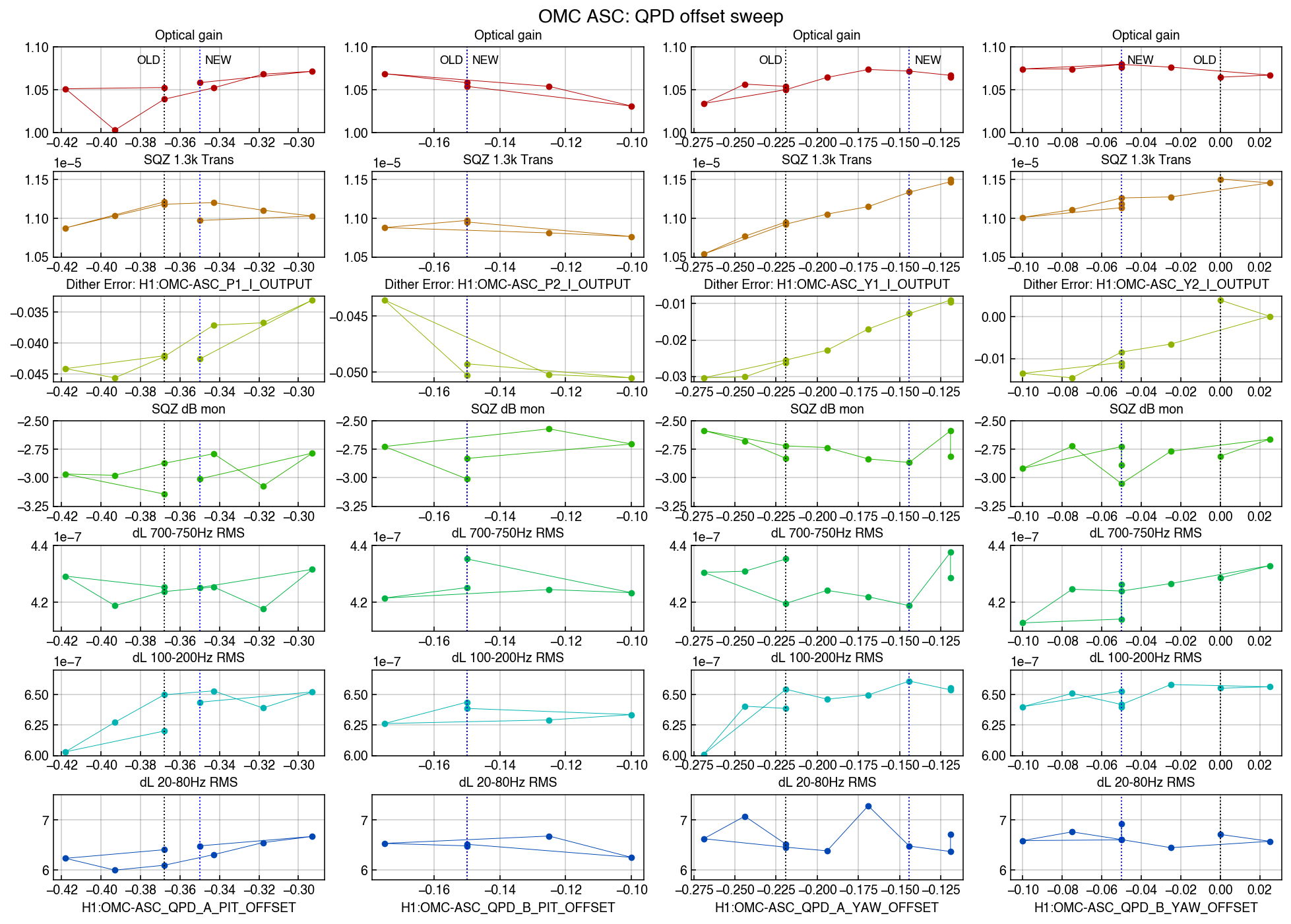
Each column shows each offset sweep (the channel shown at the bottom).
1) Optical Gain (Row 1: red)
This optical gain was obtained from the calibration system output (H1:CAL-CS_TDEP_KAPPA_C_OUTPUT) and it showed some reliable response against the offset sweep. At the time of the measurement, we were not sure where to look at, so it seems that the new nominal offsets in pitch (left two) are not optimized in terms of the optical gain yet. The ones for yaw are well optimized.
(The change of ) the actual IFO carrier mode coupling can be estimated by the suare of this value because the change of the coupling is partially compensated by DARM control at DC.
2) SQZ 1.3k trans (Row 2: orange)
This corresponds to the size of the 1.3kHz peak, which is intentionally introduced from the squeezer for the measurement. If we assume that the modes of the IFO carrier and the SQZ beam are complely matched, it works as the noise field. The reduction of the coupling of the SQZ field is again compensated by the increase of the carrier (via DARM). Therefore, this peak should show the same dependence with the optical gain (Row 1).
However, it shows different dependence from the optical gain. It could suggest that there still is misalignment (or mismatch?) between the IFO beam and the SQZ beam.
3) Dither Error signal (Row 3: yellow)
This row shows the dither ASC error output that goes into the same servo filter. I deally they should be linear to the offset sweep and should have zero crossing at the peak of the optical gain. It shows somewhat linear dependence but it was not clear if the zero crossings and the optimal optical gains were related.
4) SQZ dB / dL 700~750Hz RMS (Row 4: light green and Row 5: green)
The performance regarding the shot noise reduction was evaluated from the DARM level (however not calibrated for displacement) at around 725Hz. It was quite hard to evaluate the squeezing performance. It seemed that we experienced constant degradation of the observed squeezing level, and the dependence on the offsets were not so obvious.
5) dL 100~200Hz RMS / dL 20~80Hz RMS (Row 6: cyan and Row 7: blue)
We wanted to see the dependence of the noise level at these bands, however the dependence was not obvious. Particularly, the IFO was not at the best state during the measurement. The BNS range was constantly about 120Mpc.
Discussion
- Where to look at during the optimization
It seems that the optical gain has a clear dependence and can be a FOM for the optimization. Then the SQZ ASC can be adjusted to maxmize the SQZ level. (If it was not tried yet...)
Is it possible that, some reason, the optical gain and the squeezer have different optmized offsets???
- Sweep range
Since the QPD signals are normalized with the sum signal, it follows the error function Vout = Erf(sqrt(2) * d /w), where w is the beam size on the QPD and d is the beam displacement (cf. T1500060 Sec 3.5.2). The OMC has the beam size of ~0.5mm in radius (anywhere on the OMC breadboard).
The full range of the sweep was as much as 0.15 w.r.t. the offset. Therefore this corresponds to the beam displacement of about 50um (i.e. 1/10 of the beam radius). We were basically limited by the DAC output of the OMC SUS. Because we restrained our offset up to the 50% of the FS at the OMC SUS, there maybe a bit more room to push. Otherwise, we need to offload the bias from OMCS to the picomotors and OM1/OM2 (cf. LHO ALOG 65666)
- The QPD outputs vs offsets
The offset values we are talking about is the servo error offsets. Therefore the actual QPDs outputs have the opposite sign.
- Expected beam positions on the QPDs
This OMC (SN003) was characterized on a table top setup at Caltech. At the time, the QPD outputs were checked with the perfectly aligned beam to the OMC. According to T1500060 Sec 3.12.8, the spot positions on QPDA and QPDB are
QPDA Vert: +102um Horiz: -21um
QPDB Vert: +47um Horiz: -19um
This corresponds to the offset values
QPDA P: 0.289 Y: 0.059
QPDA P: 0.133 Y: 0.054
Because the arrangement of the QPD segments is so messed up (the OMC upside down, V and H swapped due to the PCB, the matrix compensates these), their signs are unknown. But with some assumption they are not so far from the nominal offset values. The possibility of the discrepancy from the table top measurement could come from the mode mismatch (by the IFO) between the carrier and the modulation sidebands.

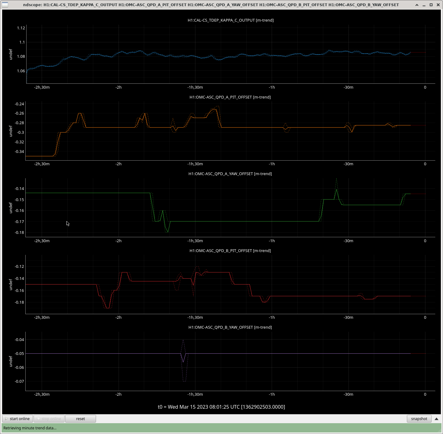
The IFO is up again and the range is good (>130Mpc) so tried more offset adjustment with regard to the optical gain optimization. Looking at H1:CAL-CS_TDEP_KAPPA_C_OUTPUT on a scope, the offsets were tweaked. Particularly, the optical gain was sensitive to A_PIT offset as the measurement yesterday shows. B_PIT offset was also tweaked. At the beginning of the adjustment, H1:CAL-CS_TDEP_KAPPA_C_OUTPUT was 1.065 and it is now almost 1.09, while a part of the increase comes from the IFO thermalization.
New nominal offsets are: (not yet saved in SDF)
  H1:OMC-ASC_QPD_A_PIT_OFFSET -0.285

  H1:OMC-ASC_QPD_A_YAW_OFFSET -0.145

  H1:OMC-ASC_QPD_B_PIT_OFFSET -0.170

  H1:OMC-ASC_QPD_B_YAW_OFFSET -0.050
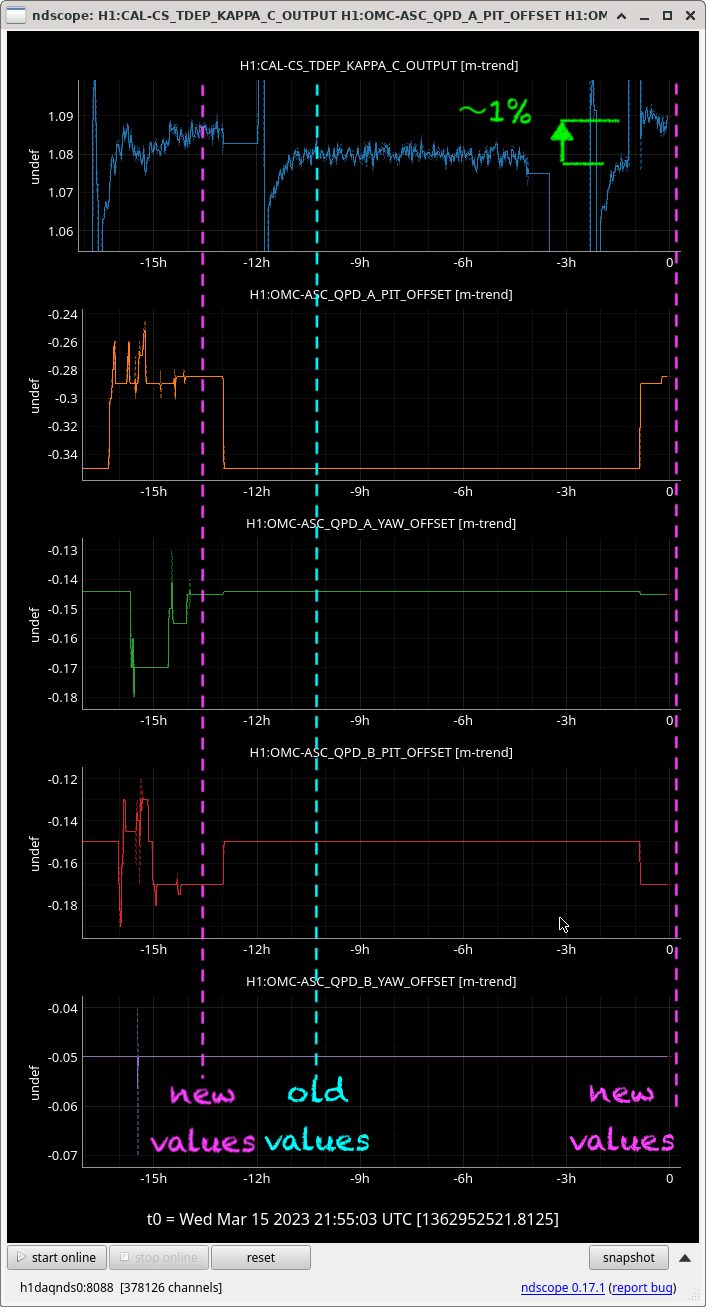
It turned out that the offsets were overridden by the prev nominal values at the lockloss at 2023-03-15 08:56:07 UTC (GPS: 1362905785).
The new values were set again on 2023-03-15 21:03:42 UTC (GPS: 1362949440) ... and a small correction at 2023-03-16 04:41:15.000000 UTC (GPS: 1362976893).
This actually made the increase of the optical gain clear. We see the increase of KAPPA_C about 1%, which corresponds to the improvement of the carrier matching by 2%.
The values were saved to safe SDF snapshot so that it automatically takes effect form the next lock. (I learned how to do it from Vicky. Thank you.)