H. Y Huang
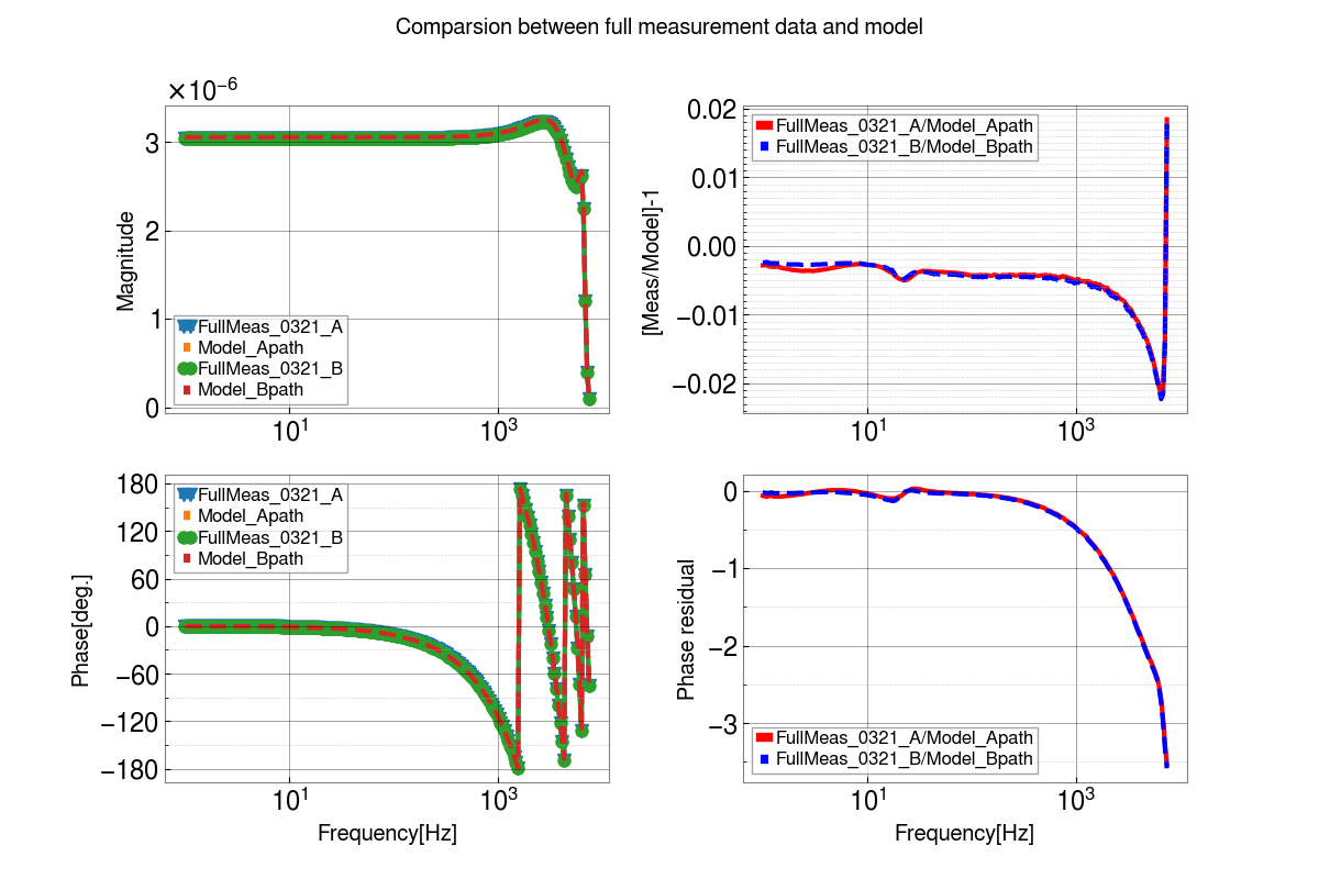
Try to investigate the sharp peak in magnitdue residual and some phase loss in high frequency region of first attachment figure that show comparsion between the measurement and model.
Due to current whitening filter design, we can easily turn off the whitening filter as BYPASS. By using two measurments taken in 21 March, I can check estimate the whitening filter and its compensation filter.
- First measurement set is 20230321_H1_TIAOnlyWhOFF_20230321CompON_OMCA_S2100832_S2300003_DCPDAandB_RemoteTestChainEXC_tf.txt
- The compensation filter for TIA is latest one.
- Component is
(1) the lsc0 DAC Drive and the (2) OMC DCPD sensing chain. In (2), no Whitening filter response and its compensation filter
- Second measurement set is 20230321_H1_TIAxWC_OMCA_S2100832_S2300003_DCPDAandB_RemoteTestChainEXC_tf.txt
- Component is
(1) the lsc0 DAC Drive and the (2) OMC DCPD sensing chain.
In this estimation, I assume time interval between two measurements are enough short, so no significant time-dependent effect was included that changes the measurement at that time. I suggest the only differnece between these two sets is whitening filter and corresponding compensation filter (NewAW) in DCPDA0 and DCPDB0.
In first measurment, we turn off whitening filter and its compensation, called WhOFF here in filename of first data set. In contrast to this, we take full DAC-driven measurement.
The right-hand side of second attachment figure shows the product of whitening and compensation filter NewAW in foton.
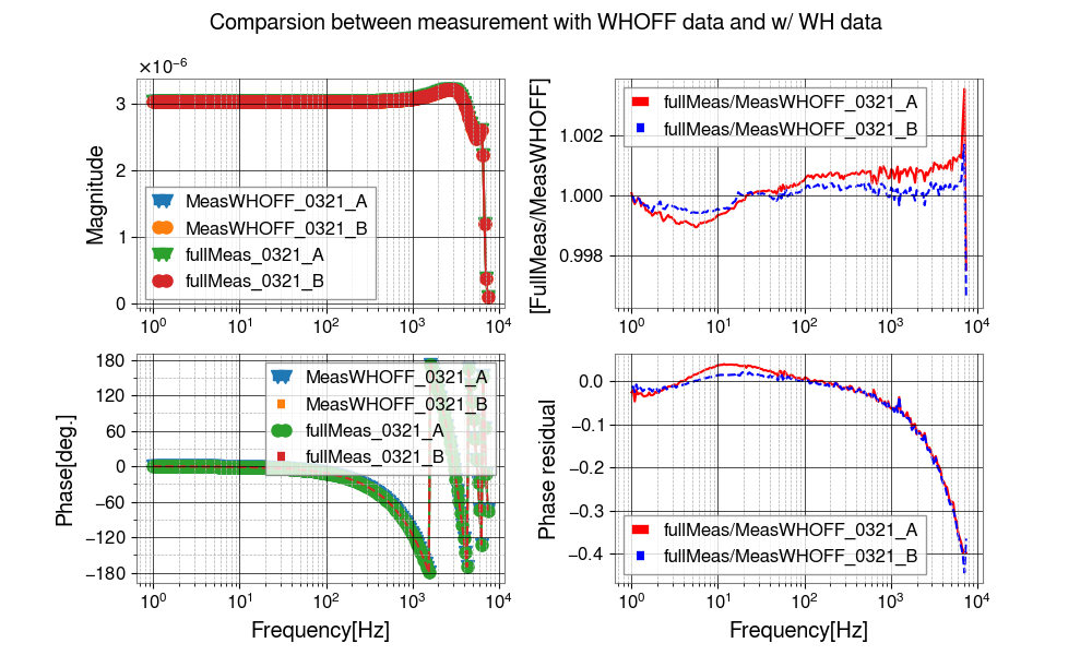
In Hsiang-yu's second plot above, there's a small frequency phase residual between the two configurations,
    (1) The whitening filters are OFF, and there's no compensation
    (2) The whitening filters are ON, and there's (low-frequency, in-loop) compensation.
to the tune of ~0.05 deg at 1 kHz.

Recall from characterization of this version of the D2200215-style whitening chassis (see LHO:67114), that there are super-Nyquist poles with the whitening filter ON at 44818.38 Hz : 44663.81 Hz, for DCPD A : DCPD B, respectively. I *believe* Hsiang-yu has accounted for these poles in his analysis (or at least used the 44500.68 : 44575.08 Hz poles that were in place from the S2300002 chassis), but there still remains an *additional* pole that is outside the range of the SR785 (i.e. above 102.4 kHz), and thus doesn't appear in the fits:
    The pole created by the feedback RC network (see attached math from a review of the O3 version of the circuit in G2000527, that's been edited for accuracy here).

Updating the component values from the newer D2200215-style chassis' filter (Drawing D2200044),
    fp_R9C6 = 1 / (2*pi*R9*C6) = 1 / (2*pi*14.3 kOhm * 10 pF) = 1112971.63 Hz.

The phase impact at 1 kHz of a 1.1 MHz pole is -- you guessed it -- 0.05 Hz:
    tf_fpR9C6 = 1 / (1 + i (f / fp_R9C6))

    real(tf_fpR9C6) = 1 / (1 + (f / fp_R9C6)^2)
    imag(tf_fpR9C6) = - f / fp_R9C6

    tf_fpR9C6_phase = atan( imag(tf_fpR9C6) / real(tf_fpR9C6) )

    phase loss @ 1 kHz = atan2d(- (1e3 / fp_R9C6), 1 / (1+(1e3/fp_R9C6)^2)) = 0.05148 deg
    phase loss @ 10 kHz = atan2d(- (1e4 / fp_R9C6), 1 / (1+(1e4/fp_R9C6)^2)) = 0.5148 deg
    phase loss @ 100 kHz = atan2d(- (1e4 / fp_R9C6), 1 / (1+(1e4/fp_R9C6)^2)) = 5.1754 deg

This is so high-frequency of an effect, we can't compensate for it easily, so instead we'll do the same as what we've done with the Transimpedance Amplifier -- for which we approximated the impact of the 3.3 MHz squeeze path with a 2.5e-6 [sec] delay (see discussion in part one of G2200551).

In this case, we'll treat the whitening chassis' 1.1 MHz pole as a 0.14e-6 [sec]:
    phase = phi_rad = 2 * pi * freq * delta_t
    -->> delta_t = phi_rad / 2*pi*freq
    -->> delta_t = (pi/180 * phi_deg) / 2*pi*freq = (phi_deg / 360*freq)

    [-0.05148 -0.51483 -5.1754] ./ (360*[1e3 1e4 1e5])
    ans =
        -1.43e-07  -1.4301e-07  -1.4376e-07
i.e. 0.14e-6 [sec].

So, what we'll do is add this delay to the pre-existing super_high_frequency_poles_apparent_delay in the pyDARM parameter file, which nowadays lives in
    https://git.ligo.org/Calibration/ifo/H1/-/blob/main/pydarm_H1.ini.
A minor detail, but ... worth understanding and including for conceptual clarity.

Note -- this pole (or its representation in the model as a delay) is only there when the whitening filter is ON. (The bypass has no response whatsoever, nothing at low, mid or high frequency.)
pyDARM can't yet handle this parameter being switchable, so for now, we'll just assume that this delay is in place since the nominal whitening state in nominal low noise is with the whitening ON.
