evan.goetz@LIGO.ORG - posted 14:36, Friday 28 April 2023 - last comment - 16:06, Friday 28 April 2023(69157)
Success computing live calibration systematic error in CALCS
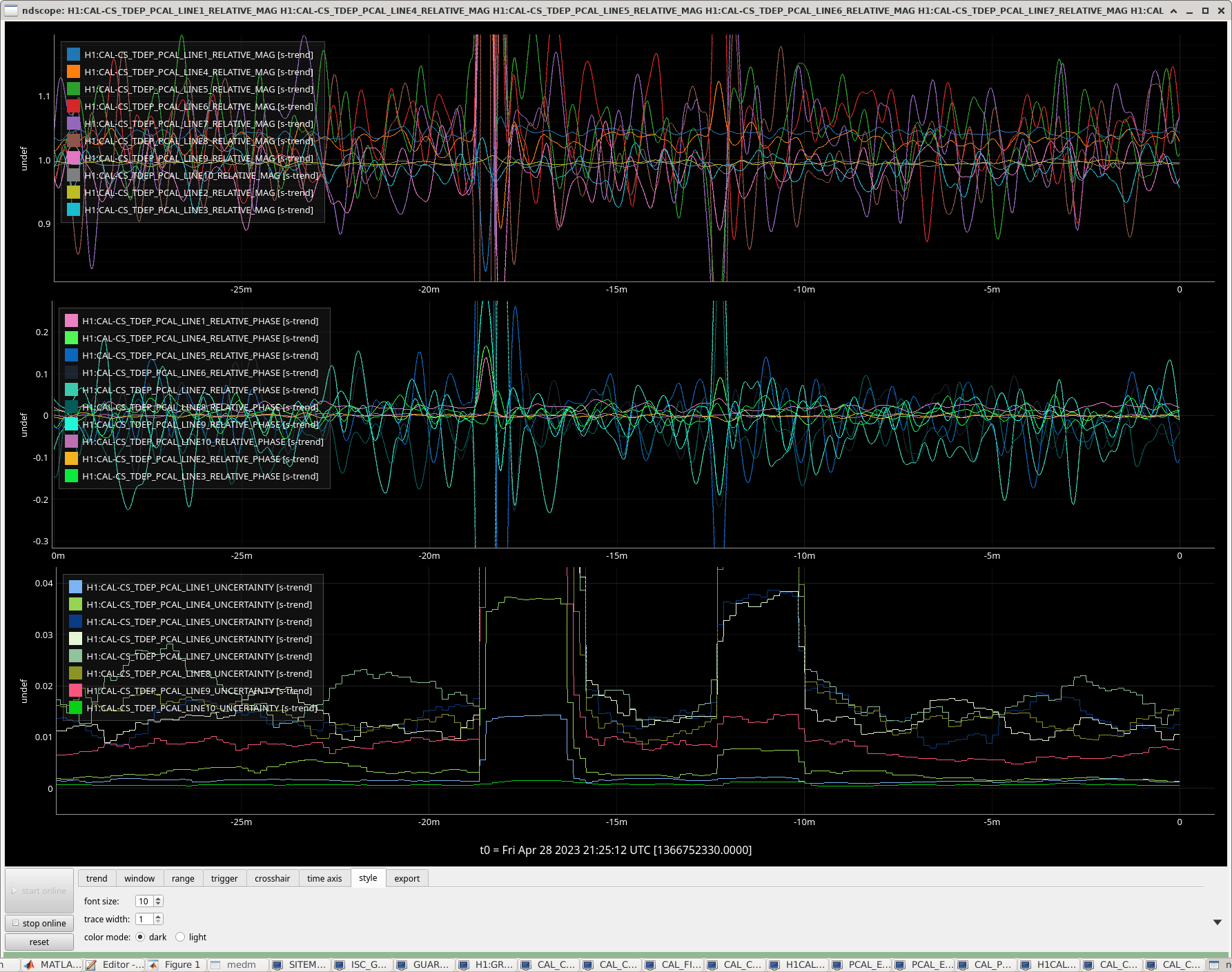
J. Kissel, E. Goetz

Executive Summary:
We are now calculating the systematic error in H1:CAL-DELTAL_EXTERNAL_DQ "live" constantly at the TDCF line and systematic error monitor line frequencies (i.e. all PCAL calibration line frequencies), and the DELTAL_EXTERNAL / PCAL transfer functions are all showing values close to 1 in magnitude and 0 degrees in phase, around ~5% deviation in magnitude, ~3 deg deviation in phase.

Details:
Some links to the details regarding the installation and commissioning the new calculation of calibration systematic error in CALCS, which only started this past Tuesday.
1) First installation on Tuesday Apr 25 2023 LHO aLOG 68961
2) Filling out the new infrastructure MEDM screens LHO aLOG 68999
3) Installing and updating DEMOD filters LHO aLOG 69112, LHO aLOG 69117, and LHO aLOG 69143
4) Populating the "DARM model transfer function values at calibration line frequencies for TDCFs and systematic error monitoring" (aka "EPICS records") LHO aLOG 69061 and LHO aLOG 69159

During the commissioning of this infrastructure, we had some trouble getting correct results, especially for frequencies below a few hundred hertz. This led us to investigate and identify a few problems.
1) one of the narrow bandpass filters for a line was incorrectly placed, but we updated it and found some consistent (incorrect) results with other frequencies (LHO aLOG 69112)
2) the values for optical gain, cavity pole frequency, and actuator gains in the pydarm_H1.ini file in the git repository and local version at /ligo/groups/cal/H1/ifo/pydarm_H1.ini did not have consistent values compared against the recently installed values in CALCS (see LHO aLOG 69047). We then updated the pydarm_H1.ini file to fix this, but we were still finding incorrect answers. The complete solution was to make sure the CALCS actuation output matrix and pydarm_H1.ini file had the same values for the x-arm: -1. ***
3) The "human vs. machine modification of parameter file" loop needs to be closed after an MCMC result gets pushed to the front end CALCS model. Meaning, the parameter file needs to get updated values before calculating TDCFs, otherwise TDCFs calculated from this parameter file directly will create invalid calibration results, without us realizing it.

Now we have finally sorted this out, the values produced by the calibration systematic errors are starting to look pretty good. Note that this is a measurement of the systematic error on H1:CAL=DELTAL_EXTERNAL_DQ corrected for the known static systematic errors GDS/CALCS (mostly impacting at high frequency for super-Nyquist poles), but does not correct for any time dependence of the interferometer.

Attached are two figures showing the systematic error calculated via this new infrastructure for today.
    - 2023-04-28_SYSERROR_LINES_FirstResults_30minutetrend.png shows a 30 minute trend of the channels. There will be lots of further, standard, improvements we can make to these demod outputs that we'll likely implement over the next week. But, one can clearly see that lines with the higher SNR in DARM show nice clean answers. Here, the phase is in radians.
    - 2023-04-28_SYSERROR_LINES_FirstResults.pdf since we're far more used to looking at the systematic error in the frequency domain, we took a 180 sec average of the systematic error answers and then transposed them by hand on to a bode plot. This conveys the same result -- the louder PCALY "TDCF" lines have a lower uncertainty than the quieter PCALX "Systematic Error" lines. Also note that the phase in this plot is in degrees.

Either way, one can see  the magnitude is 1 +- 0.04, with a noise of ~10% and phase is 0 +/- 2 degrees with a noise of ~5 deg. Go team!

Note that this is not the normal multiplicative systematic error (aka "eta values") because it is DELTAL/PCAL. This is the inverse of an eta, so to correct the DELTAL you need to divide by these values. Tricky.

*** There had been some previous discussions (see the latter pages of G2300832) indicating that to get correct GDS filters required the CALCS values to be -1 and the pydarm_H1.ini file to be +1. This does not appear to be true, at least for the EPICS records installed in CALCS. This may mean that either GDS is doing something to include a -1 where it should not, there is a mistake in a method used by GDS to export transfer functions from pyDARM, or it could mean that an ini file previously used to generate GDS filters were using incorrect values and we need to solidify/sort out which copy of the parameter file is the parameter file. Further investigation is needed here!
Images attached to this report
Non-image files attached to this report

Comments related to this report
Here's the map of calibration line frequency to DEMOD names (LINE${n}), and the channel names for the magnitude, phase, and uncertainty.


17.1        H1:CAL-CS_TDEP_PCAL_LINE1      _RELATIVE_MAG     _RELATIVE_PHASE     _UNCERTAINTY
24.5        H1:CAL-CS_TDEP_PCAL_LINE4            |                   |                 |
33.43       H1:CAL-CS_TDEP_PCAL_LINE5            |                   |                 |
53.67       H1:CAL-CS_TDEP_PCAL_LINE6            |                   |                 |
77.73       H1:CAL-CS_TDEP_PCAL_LINE7            |                   |                 |
102.13      H1:CAL-CS_TDEP_PCAL_LINE8          (same)                |                 |
283.91      H1:CAL-CS_TDEP_PCAL_LINE9            |                   |                 |
410.2       H1:CAL-CS_TDEP_PCAL_LINE10           |                   |                 |
410.3       H1:CAL-CS_TDEP_PCAL_LINE2            |                   |                 |
1083.7      H1:CAL-CS_TDEP_PCAL_LINE3            V                   V                 V

Recall that the uncertainty, UNC, in radians, is derived from the coherence, C, where UNC = sqrt(1-C / 2 * Navg * C)), where "Navg" is set by the H1:CAL-CS_TDEP_COH_BUFFER_SIZE channel, and the FFT length, set by H1:CAL-CS_TDEP_COH_STRIDE, should match the corner frequency of the low pass that's used in the DEMODs.

Some further notes:
    - the 24.5 Hz line is a part of the temporary collection to monitor how thermalization of the IFO impacts systematic error during the engineering run, so that DEMOD and its line will be turned off for the remainder of the run.
    - the 17.1 and 410.3 Hz are a part of the determination of time-dependent correction factors. Though the answer, [[ DELTAL_EXTERNAL * (GDS / CALCS) ]] / PCAL is NOT corrected for TDCFs, the answer from these two lines is kind of "in loop" for GDS-CALIB_STRAIN, which DOES correct for TDCFs.
    - All lines other than the 24.5 Hz are now expected to be permanent, and continue through into O4, as per LHO:68289.