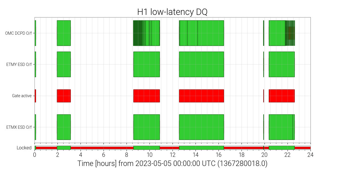
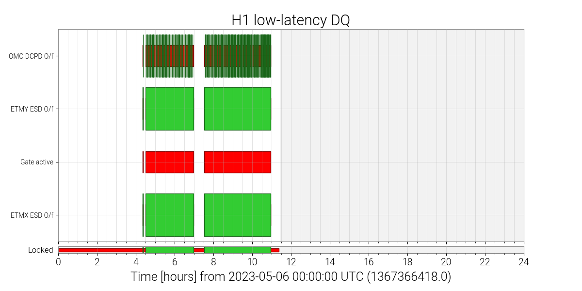
Tito Dal Canton from PyCBC reported that there are periods with many ADC overflows of the DCPD in the last few days. This is probably due to the increased DARM offset alog 69358. See attached plots of the DQ vector. There's no obvious effect on the spectrum or the glitchiness, so it must not be a severe overflow. But at least some of the searches are using this as a veto and aren't analysing the data.
What is this triggered on? The attached plots show the DCPD min/max monitors for the same time. There are saturation events at the beginning (violin modes) and at the end of locks (lock loss), or during lock attempts, there are no saturations visible once the instruments have stabilized. One can also see some larger values during the most recent lock, which are still below saturation and which might be violin modes or parametric instabilities.
The plotted channels are 16 Hz EPICS channels that are caluclated in the front-end using data at the full converter rate (219 Hz). For each DCPD channel 4 18-bit ADC channels are getting summed to form a 20-bit word. Saturation happens once the sum channels reach ±219 counts. Since individual ADC offsets and gains could be slighlty different, a saturation monitor should propbably trigger around ±500,000.
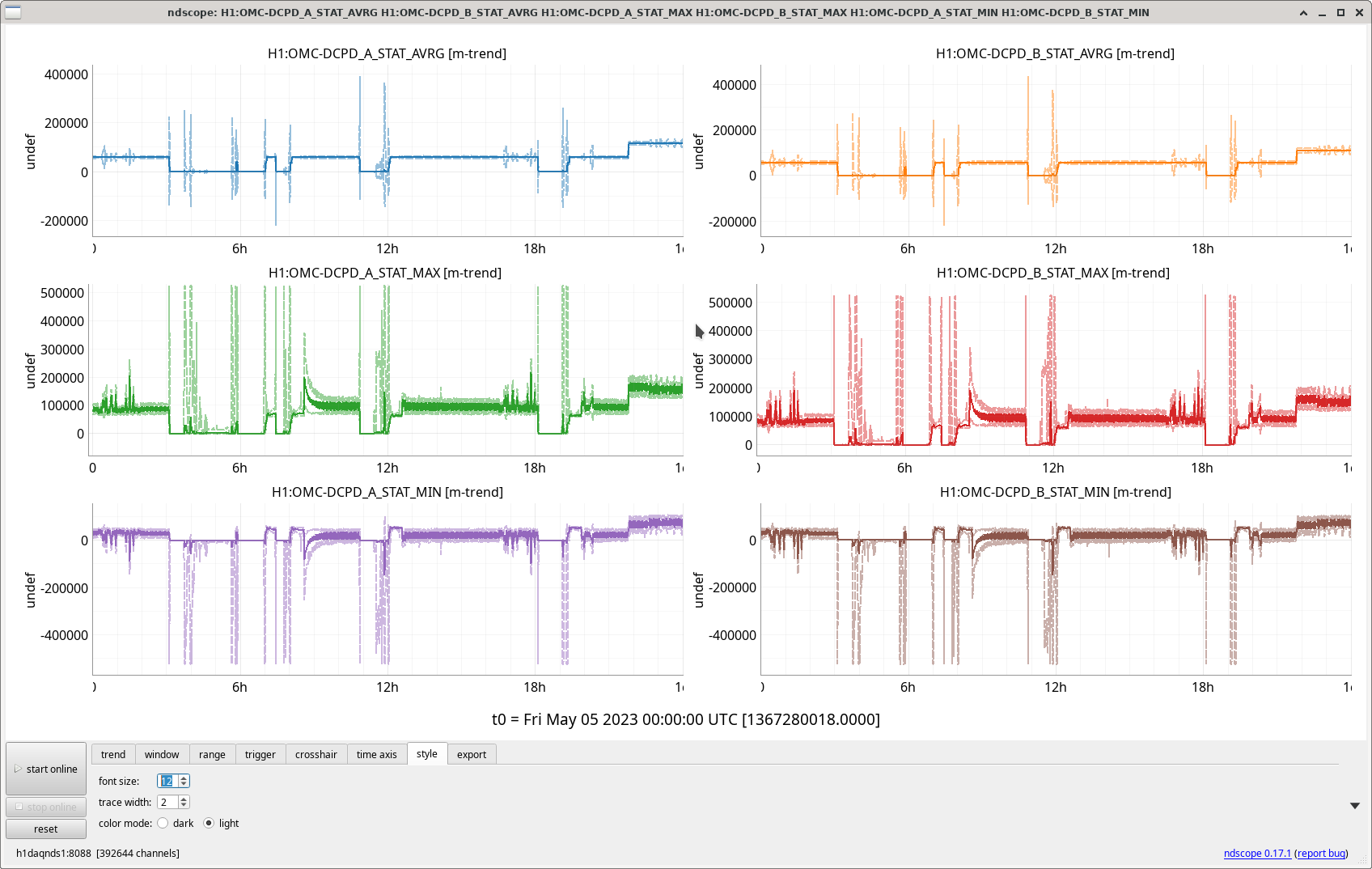
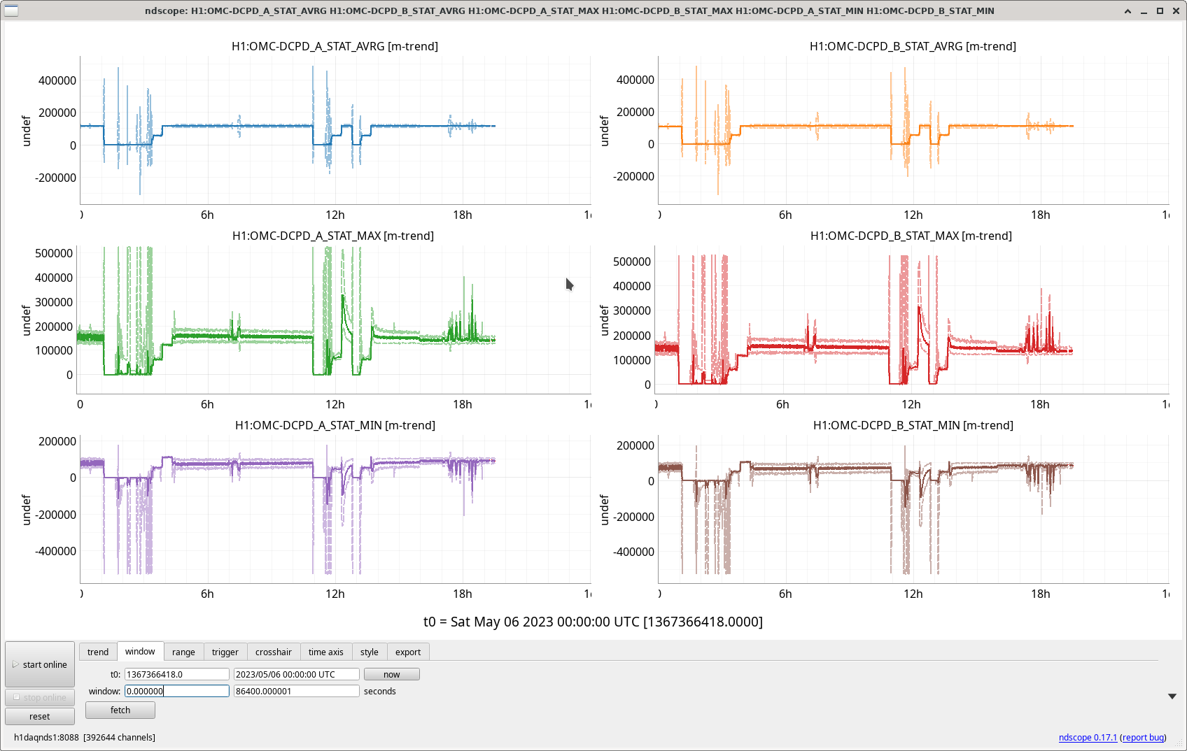
It will just be using the overflow channel calculated in the front end, H1:FEC-8_ADC_OVERFLOW_0_12 and 0_13 for DCPD A and B. The Simulink models that are exported show those as the only ADCs for the DCPDs, but they haven't been updated since 2022-07. Looking at the traces closely, the overflows do seem to be reported whenever STAT_MAX goes over ~2^17.
No sure what this indicates, seems wrong. Use H1:FEC-179_ADC_OVERFLOW_0_x with x = 0, 1, 4, 5, 8, 9, 12, and 13 instead.
Indeed, filling out Daniel's description:
This is one of the major changes to the detector for O4 -- the OMC DCPD signal processing chain is entirely different.

At LHO, we're reading out the same two in-vacuum OMC DCPDs with
    - A brand new low-noise transimpedance amplifier
    - A brand new whitening chassis
    - *no* analog anti-aliasing filter, but making 4 analog copies of the two input voltages
    - digitized with a brand new, lower noise, 18- (instead of 16 bit), 32 channel (instead of 16) ADC, sampled at 524 kHz, in an entirely new "segregated" IO chassis,
    - whose digital signal is created with a brand new real-time code Input-Output processing architecture -- whose DCUID is 179, hence H1:FEC-179_ADC_OVERFLOW_0_x with x = 0, 1, 4, 5, 8, 9, 12, and 13  -- that is "sampling" the 524 kHz voltage from the ADC at 65 kHz (i.e. grabbing 8 samples each 65 kHz clock cycle)
    - a new time-stamping system correlated with the DAQ, such that the data is *time stamped* as though its 5x 524 kHz clock cycles (i.e. 9.6 usec) behind all other data in the CDS architecture

After digitization, each channel's 4 copies are coherently summed, then divided by 4.0 in order to average the signal coherently across the 4 ADC channels (and thus improving the noise further by reducing the coherent digitization noise by sqrt(4)). Then, each averaged channel is
    - signal conditioned in new filter banks (running at 524 kHz)
        H1:OMC-DCPD_A0
        H1:OMC-DCPD_B0
    where the signal conditioning includes conversion from ADC counts back into milli-amps of current from the DCPDs via
        i. inversion of the measured transimpedance amplifier response
        ii. inversion of measured analog whitening response
        iii. inversion of the ADC "gain", now 2^18 ct / 40 V
        iv. two digital anti-aliasing filters, one for 524 kHz to 65 kHz, and one for 65 kHz to 16 kHz
and then that down-sampled, conditioned 524 kHz is shipped over inter-process communication to the old h1omc front-end model (with DCUID 8  -- i.e. H1:FEC-8_ADC_OVERFLOW), where it marries with identical 16 kHz digital infrastructure from O3 (save the *lack* of signal conditioning in 16 kHz the H1:OMC-DCPD_A and H1:OMC-DCPD_B filter banks because their function is now in the 524 kHz IOP model).

Please check out LHO:67644 for all the current digital version of the OMC DCPD channels.

Apologies that we've not yet had time to present this formally to all members of the collaboration repeatedly, as it was not until ~2 months ago that all this was settled. Information is stil scattered across aLOGs, to be gathered for review documentation.
And, naturally, only a portion of this is true at LLO. (They're still using a 65 kHZ analog AA filter, not using segregated IO chassis, and they're shipping from the 524 kHz IOP model to 16 kHz OMC model directly, rather than over IPC so their 524 kHz data is stamped as though it is 3 524 kHz clock cycles = 5.7 usec *ahead* of all the other CDS channels).

Note, all of these changes are "calibrated out" of the data stream, so down stream data analysis need not know *anything* about this, nor treat the calibrated data stream any different.
But -- *that* why the number to look at for ADC saturation has changed.
We have found an issue, with the calculation of the ADC limit in user models. User models are not accounting for 18 bit ADC values, and are erroneously reporting ADC overflows.

IOP models do have the proper logic. Can you switch the channel you use to check for overflows to the one provided by h1iopomc0?

Example:  H1:FEC-179_ADC_OVERFLOW_0_12 instead of  H1:FEC-8_ADC_OVERFLOW_0_12