stefan.ballmer@LIGO.ORG - posted 23:33, Friday 05 July 2013 - last comment - 17:18, Saturday 06 July 2013(6990)
Cavity Mode Scan
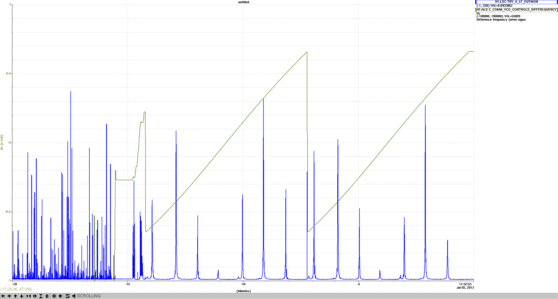
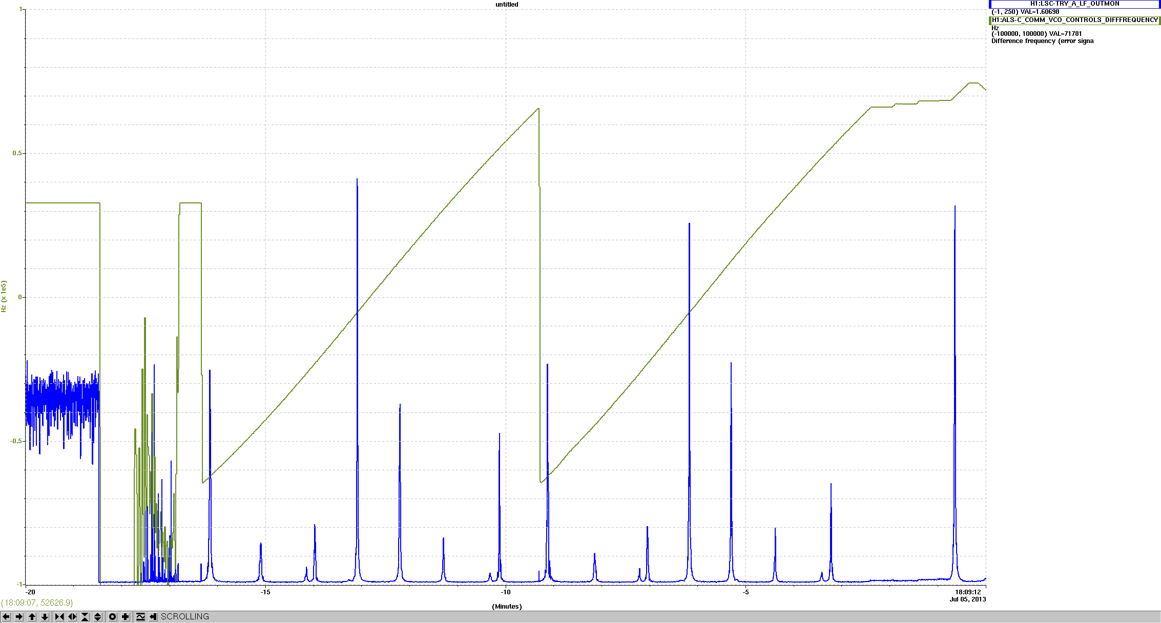
(Daniel, Stefan)

First we realized that the 10x higher fluctuations we obserbed on Wednesday were entirely due to alignment. So we tweaked up what we thought was the carrier, and indeed reproduced the ~8Hz RMS performance.

At this stage we rand a mode scan (attached, plots 1 sand 2). The two attached plots are from two adjacent locks - they differ by 1/2 FSR, as expected.
For the 2nd one, the modes sit at

H1:ALS-C_COMM_VCO_TUNEOFS = [-4.744, -3.242, -1.882, -1.638, -0.380,  0.877,  2.187,  3.557,  3.837,  5.348]  V
Frequency offset           =[-62075, -44240, -26212, -22842, -05055,  12770,  30803,  48585,  52070,  69855] Hz

The transverse mode spacing 8945Hz ( 17890 Hz on the VCO)
The odd this is that the frequencies make most if the 10 mode is the biggest.

We also redid the transmon camera and LSC diode, taking out the ND filter which distorted the view. While the new image is not distorted, we still don't get a nice modal picture. Not sure why.
Images attached to this report
Comments related to this report
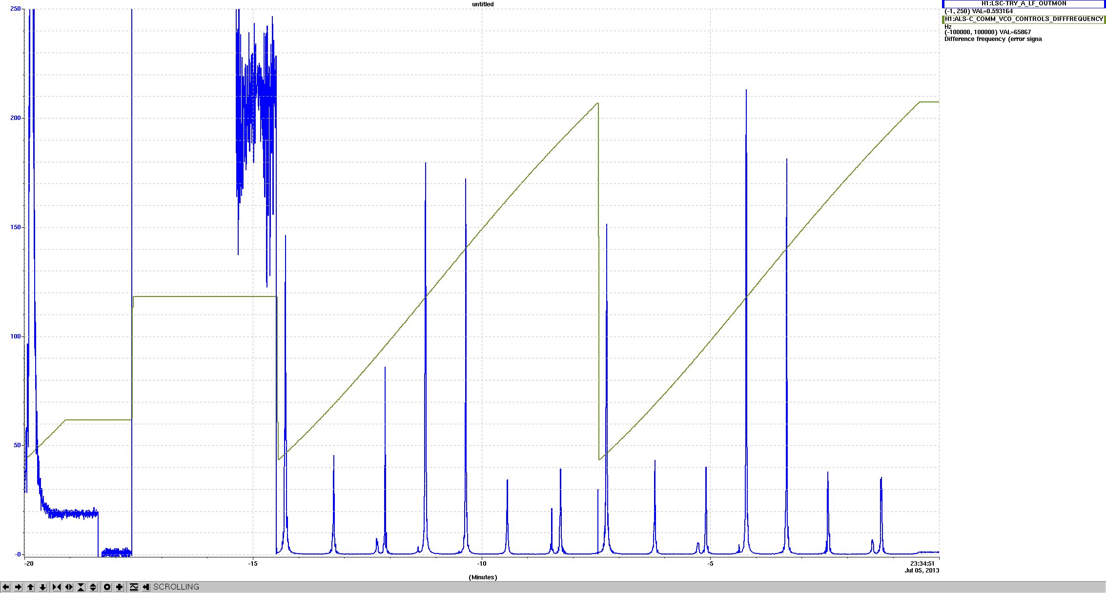
Here is another mode scan after the alignment drifted off more.

We now suspect that we maximized the wrong mode.
Images attached to this comment
Do the frequencies all add up? With a curvature of 2300 m and a cavity length of 4000 m, the individual g parameters are -0.739. The transverse mode spacing then becomes cos-1–(g2 g2)1/2 = 0.765. Multiplying by the FSR, we get 28.7 kHz. Or, –8.8 kHz, if we subtract one FSR. The green cavity field is upshifted relative to the corner. This means that the mode at the smallest apparent scan frequency is the 00 mode.