Jenne, Sheila, TJ
When operating with 75W input power, we had been using a thermalization guardian to increase the PRCL gain as the 9MHz gain dropped during thermalization. Today we did a series of PRCL OLG measurements as the interferometer thermalized, and see that the PRCL optical gain is still dropping but not nearly as much. For now, Jenne and TJ have set the guardians to no longer use the thermalization guardian, so it's nominal state is DOWN.
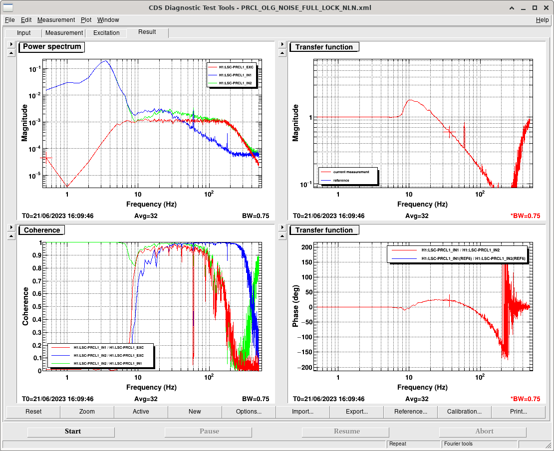
Our first PRCL gain measurement posted today 70659 was taken 24 minutes after reaching 60W input power, with a digital gain of 6 gave us a 25Hz ugf. After the thermalization was complete Jenne found that a digital gain of 10 gave us a ugf of 30Hz. The attached screenshot was that first measurement, showing that a digital gain of 10 would have been stable at this time. Jenne has put the digitial gain of 10 into the guardian to happen in the state LOWNOISE_LENGTH_CONTROL, we think this should be OK. For comparison, at 75W input power the thermalization guardian took the PRCL gain from 6 to 37, so this thermalization is much less extreme.
If there are any problems with locklosses at LOWNOISE_LENGTH_CONTROL or shortly after, it may be that the PRCL gain is too high. A temporary solution in this case would be to just wait ~25 minutes after reaching 60W input power before doing LOWNOISE_LENGTH_CONTROL, ie, wait at LOWNOISE_ASC for 20 mintues or so. If this happens we will find a solution in the guardian tomorow.