It seems that the OMC single bounce mode matching is better with hot OM2 than it was with the similar measurement 70409
Daniel turned off the sidebands and manually aligned the locked OMC.
- locked OMC, sidebands off: 1371920979 to 1371921080 (16.15 mA OMC DCPD sum, OMC refl is roughly 1.84mW average, minimum roughly 1.76mW)
- unlocked OMC sidebands off: 1371921192 to 1371921317 (OMC REFL rough average 22.6mW)
- scan time: 1371921531 duration 100 seconds. screenshot attached. from cursor 00 mode 16.28mA 20/02 0.73mA)
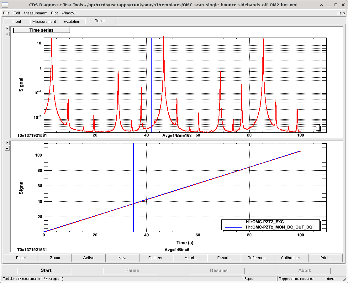
I used an adpated version of the OMCscan class to fit the spectrum up to 20/02 carrier modes. The scan went through two free spectral ranges so I just used the first 60s to make the analysis easier, and assuming that within this 60s of data the third smallest clear peak was 20, and the fourth one was 10 mode.
The fitted spectra is attached.
Then I used an adapted version of fit_two_peaks.py to fit a sum of two lorentzians to the 20 and 02 carrier modes, the fit is shown in the second graph.
We expect the HOM spacing to be 0.588 MHz as per this entry and DCC T1500060 Table 25.
The spacing for the modes measured is 0.549 MHz.
From the heights of the two peaks this suggests mode-mismatch of the OMC to be C02+C20/C00 = (0.457mA+0.629mA)/(16.39mA+0.457mA+0.629mA) = 6.2% mode mis-match.
From the locked/unlocked powers on the OMC REFL PD the visibility on resonance is 1-(1.84mW/22.6mW) = 92% visibility.
If the total loss is 8%, this implies that the other non-mode-matching losses are roughly 1.4%.
To run the OMC scan code go to
/ligo/gitcommon/labutils/omc_scan/ and run
python OMCscan_nosidebands2.py 1371921531 60 "Sidebands off, 10W input, hot OM2" "single bounce" --verbose --make_plot -o 2
in the labutils conda environment and on git branch dev.
To do the double peak fitting run:
python fit_two_peaks_no_sidebands2.py
in the labutils conda environment and on git branch dev.


This was a single bounce scan off ITMX, with 0.44W on the ring heater upper and lower segments, and no CO2.
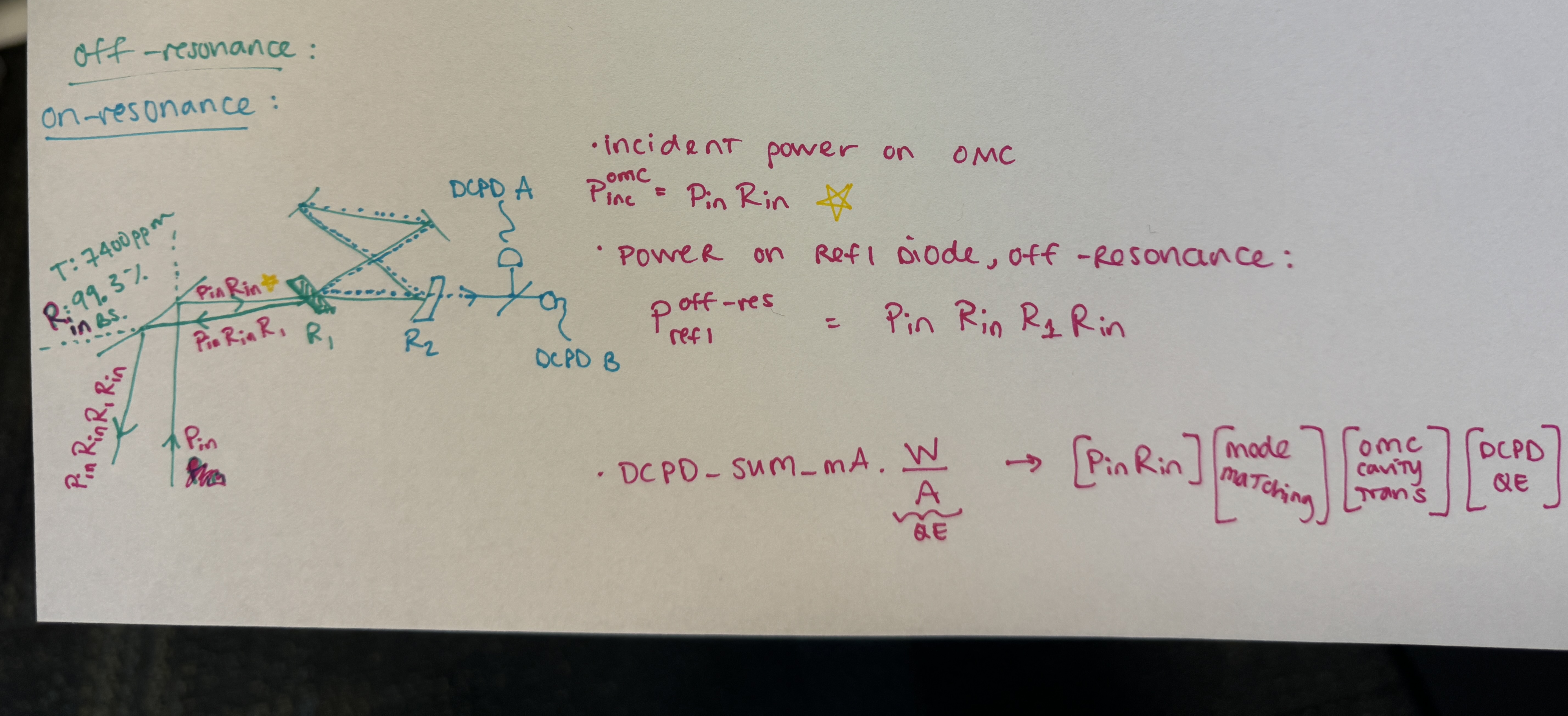
Using Jennie's mode mismatch of 6.2%, we can use the ratio of locked vs unlocked reflected power to estimate the OMC losses, finesse and transmission for a perfectly mode matched beam.
I've used a time when the fast shutter was blocked from 70409 to subtract the dark offset the refl diodes, this gives reflected power on resonance of 22.61mW, reflected power off resonance of 1.85mW.
The power in the mode mismatch is reflected_power_off_resonance * 6.2% = P_mm 1.4mW
Visibility for the 00 mode is (refl_on_resonance - P_mm)/(refl_off_resonance - P_mm) = 2.1%
The attached script uses this visibility to find the loss using:
def Refl_fraction(r_loss):
on_res = (r1 - (t1**2 * r1 * r_loss)/(1-r1**2*r_loss))**2
off_res = (r1 + (t1**2 * r1 * r_loss)/(1+r1**2*r_loss) )**2
return on_res/off_res
with r1 = sqrt(reflectivity of the input output mirrors) = sqrt(1-7690e-6) from T1500060 page 143, and r_loss = sqrt(1-round trip losses). With a visibilty of 2.1% this gives us a round trip loss of 2616ppm. If true this level of loss would imply a finesse of 351, well lower than previous measurements: 69707. This would imply that the transmission of the OMC cavity for a 00 mode is 73%.

Koji pointed out that infering losses from the visibility as I did above is very sensitive to the HOM content, and including the first order modes above would have resulted in a different value of OMC losses.
As an alternative approach, I adapted a mathematica notebook that Koji shared to use the transmitted power along with the visibility, and infer higher order mode content and cavity transmission by making an assumption about the DCPD QE.
One confusing point about using these reflected power measurements is that we have to correctly take into account that the beam which arrives at the OMC REFL path has reflected twice off the QPD pick off beamsplitter. (So, the incident power on the REFL diode = incident power on OMC breadboard/ R_pick_off^2)
The results we get for cavity losses (and higher order mode content) depend on what we assume for DCPD QE with this method. Below are the results of the attached script run with a QE of 1 and a QE of 96%, this only makes a small change in the higher order mode content we infer, and that small change in HOM also causes a small change in what we infer for the total efficiency of the OMC breadboard in the two cases.
Power on refl diode when cavity is off resonance: 22.612 mW
Incident power on OMC breadboard (before QPD pickoff): 23.052 mW
Power on refl diode on resonance: 1.848 mW
Measured effiency (DCPD current/responsivity if QE=1)/ incident power on OMC breadboard: 81.6 %
assumed QE: 96.0 %
power in transmission (for this QE) 19.598 mW
HOM content infered: 8.069 %
Cavity transmission infered: 93.376 %
predicted efficiency () (R_inputBS * mode_matching * cavity_transmission * QE): 81.616 %
omc efficency for 00 mode (including pick off BS, cavity transmission, and QE): 88.780 %
round trip loss: 540 (ppm)
Finesse: 396.346
assumed QE: 100 %
power in transmission (for this QE) 18.814 mW
HOM content infered: 7.903 %
Cavity transmission infered: 89.479 %
predicted efficiency () (R_inputBS * mode_matching * cavity_transmission * QE): 81.616 %
omc efficency for 00 mode (including pick off BS, cavity transmission, and QE): 88.620 %
round trip loss: 886 (ppm)
Finesse: 388.021