[Stefan and Kiwamu]
We handed the CARM control from the green ALS beatnote sensor over to the REFL infrared demodulated signal. This worked well.
In this configuration, the PSL frequency was locked to the arm cavity and no green light was involved any more. The lock stayed for more than 20 minutes and was long enough to do some further noise investigations.
Update on Noise plot:
We tested two configurations :
-
(A) ordinary HIFO CARM noise setup .
- CARM is controlled via the ALS green beatnote and the red demod signal serves as an out-of-loop sensor
-
(B) Infrared control configuration:
- CARM is controled via the infrared REFL demod signal and the ALS beatnote serves as an out-of-loop sensor
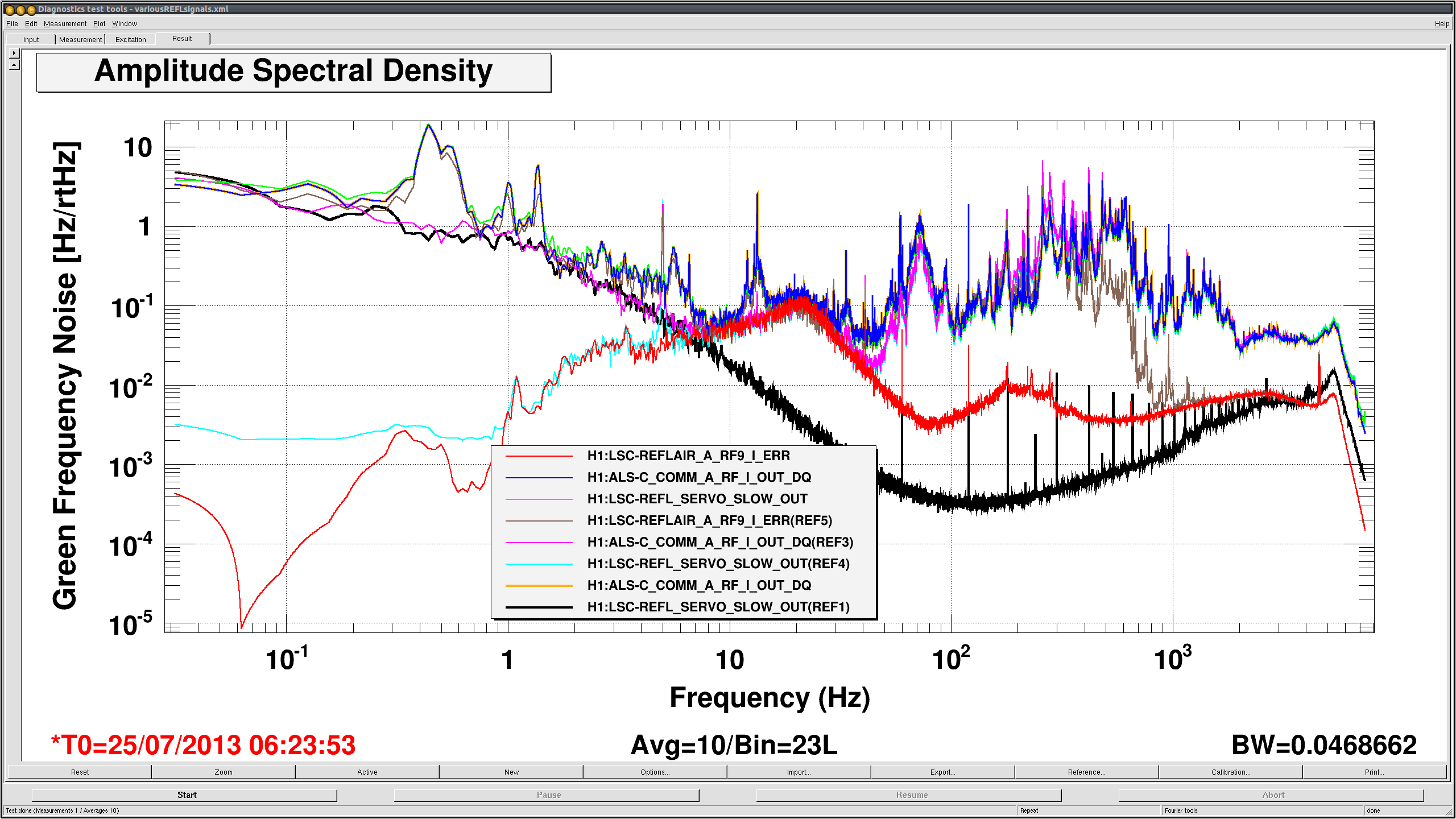
In both cases we have three sensors to evaluate the noise performance. We had two channels for the ALS beatnote, which are REFL_SERVO_SLOW and ALS-C_COMM_A_RF_I. The difference is that COMM_A_RF_I is digitized before the common mode board and REFL_SERVO is digitized after the board. Ideally they should be always the same. The last signal is the infrared signal, REFLAIR_A_RF9_I, which is the one derived from the reflected light off of the arm cavity and demodulated at 9 MHz.
Configuration (A)
(Red): The infrared sensor. Therefore this is the in-loop signal for CARM
(Blue): Beat signal at ALS-C_COMM_A_RF_I. Out-of-loop.
(Green) : Beat signal at LSC-REFL_SERVO. Out-of-loop.
Configuration (B)
(Brown): The infrared sensor. Out-of-loop
(Pink): Beatnote at ALS-C_COMM_A_RF_I
(Cyan): Beatnote at LSC-REFL_SERVO. This is the in-loop error signal
Some other noise
(Black): beat-note readout electronics noise at LSC-REFL_SERVO
What we did:
-
Calibration of ALS-C_COMM_A_RF_I into green beat frequency.
- This was done by tweaking the filter modules to reflect the current SR560 setup which is out of the VCO PLL.
-
Calibration of REFL_SERVO_OUT into the green beat frequency.
- This was done by comparing this signal with ALS-C_COMM_A_RF_I and making it identical with the digital filters in the LSC front end.
-
Calibration of the LSC-REFLAIR_A_RF9_I into the green beat frequency.
- This was done by multiplying a factor of 2 in its gain since this was already calibrated to the infrared frequency.
-
We re-edited the handing script, CARM_hanoff to reflect these changes.
- We confirmed that the script runs fine.
- Then we engaged the ALS CARM servo as usual.
- We brought the PSL frequency to a resonance of the infrared light in the arm cavity by fiddling with the COMM VCO.
-
Hading over the signal from that of ALS to the REFL infrared signal
- This was done by simultaneously zeroing LSC-REFL_SERVO_OUT_GAIN and increasing the LSC-REFLAIR_A_RF_I_GAIN in 5 seconds.
- There was no problem since the signals were all identical due to the calbration.
-
Apart from ALS and CARM, we tried to calbrate the MC2 M3 suspension actuator by using the green beatnote as a reference.
- According to Jeff.K the M3 actuator should have a response of 1.5e-15 m/cnts at 20 Hz.
- However we measured it to be 6e-16 although this is not accuate since the value varied in every measurement.

Attached is the attempt to calibrate MC2 using the beat-node signal. The horizontal bar is at 6e-16m/ct.
The variability is most likely due to saturation. Without frequency feed-back the beat-node signal tends to run into its range limit.

The calibration should be redone with the REFLAIR diode.
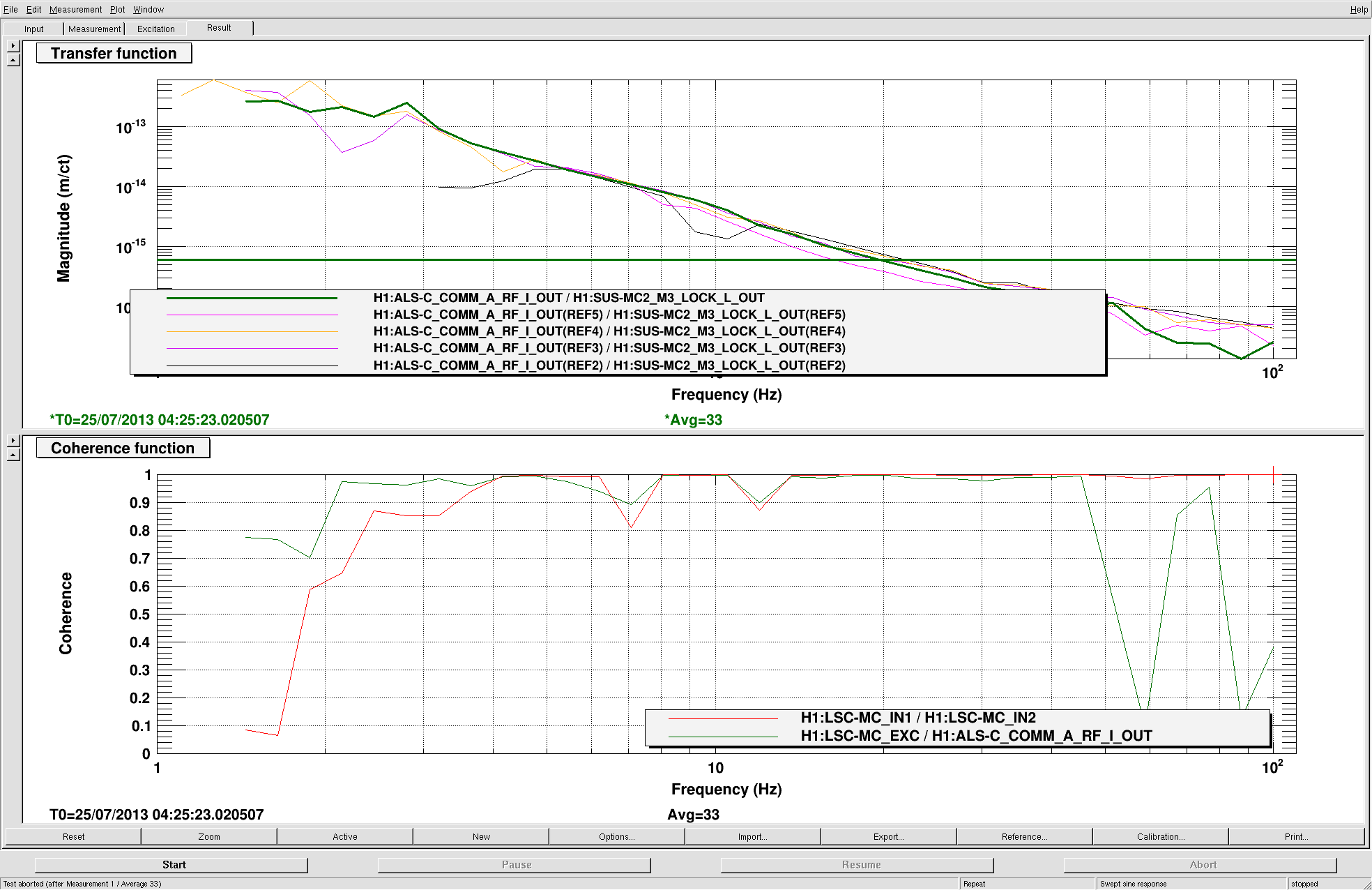
Here's the plot I'd made to re-create this transfer function in the model, as requested by Kiwamu and Stefan.
Some additional items:
- the REFLAIR_A_RF9_I was calibrated into Red Hz by adding a filter with a gain of 82Hz/(2*1000cts) and a z82:p1e3 cavity pole compensator.
- We noticed the the green PDH error sigal at EY (as seen at the analog Imon signal from the demos board) has about 2.5Vpkk signal at ~28kHz. Given that it sometimes bleeds over into the Q sigal, I am pretty sure that we are saturating an RF amplifier before the demos board.