lisa.austin@LIGO.ORG - posted 10:19, Friday 26 July 2013 (7241)
SLC - Manifold Cryopump assembly and installation
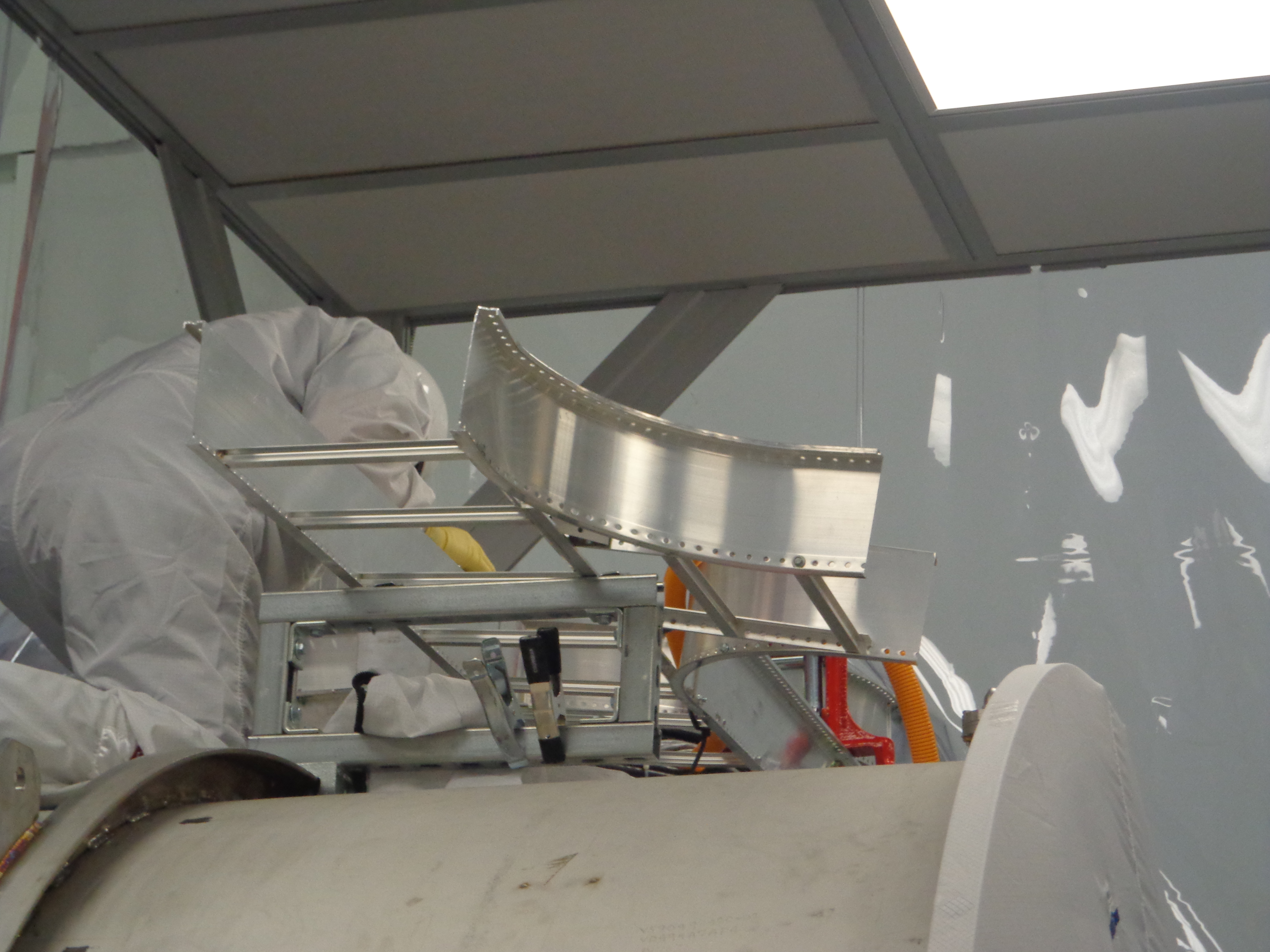
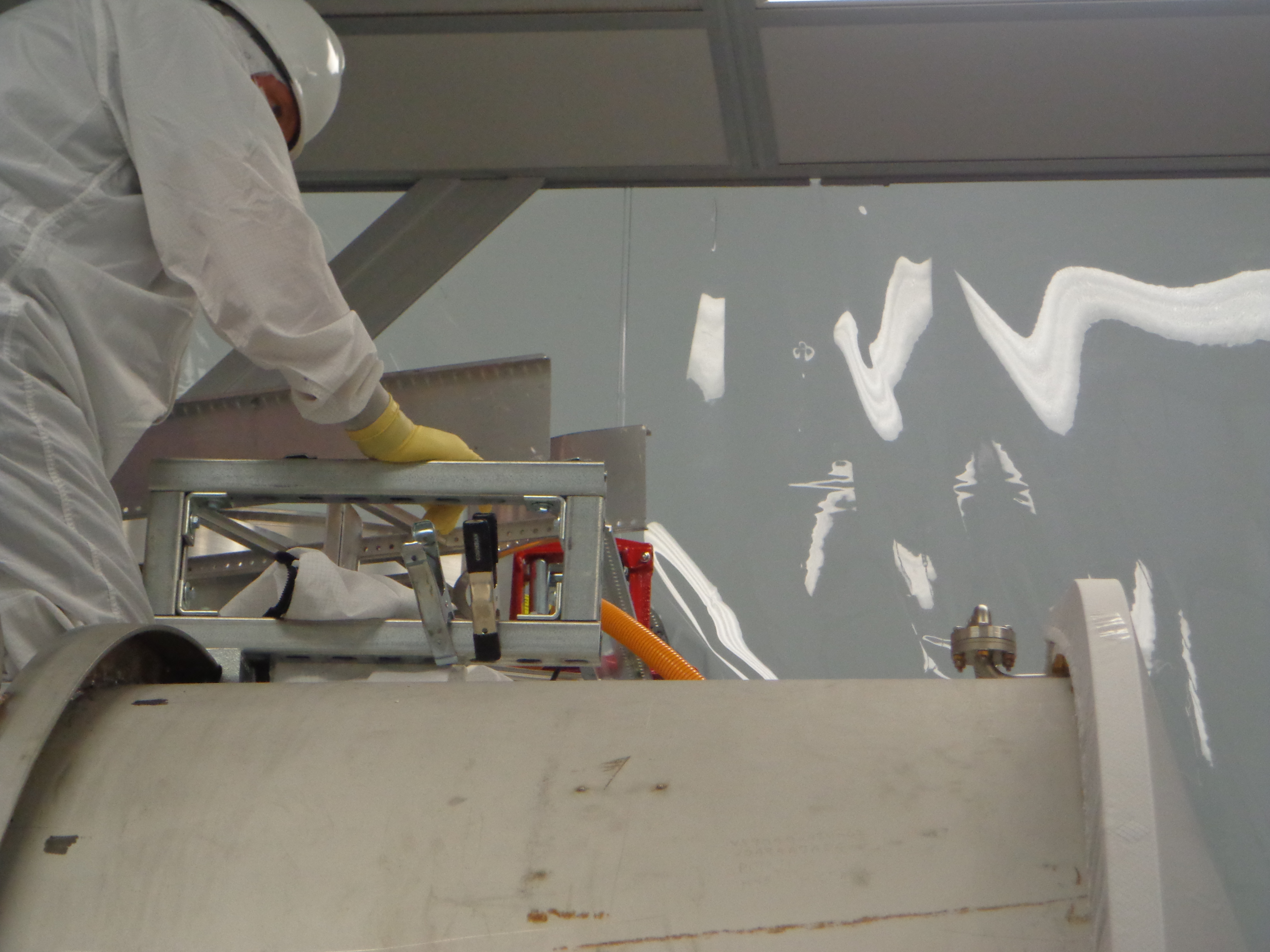
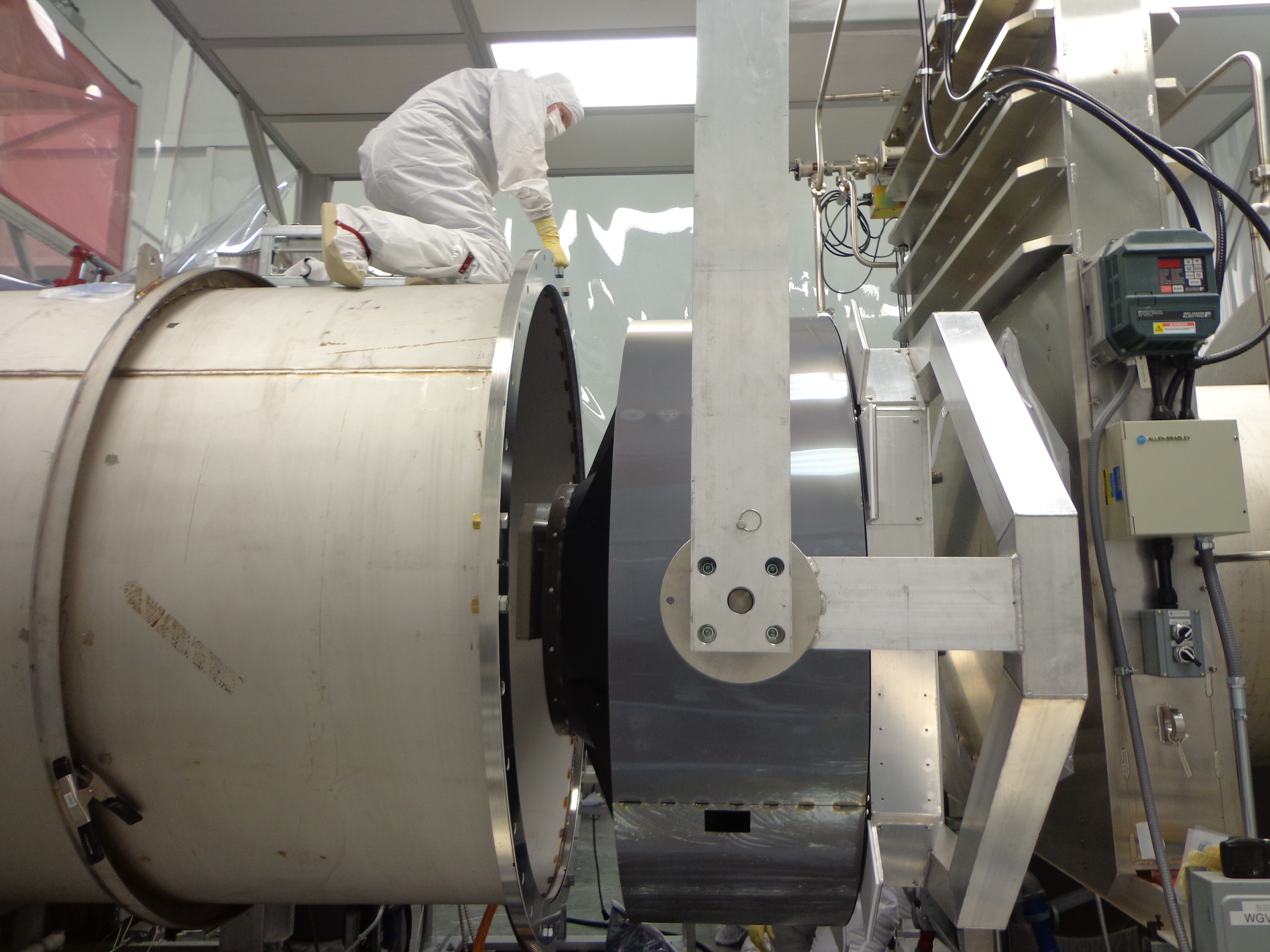
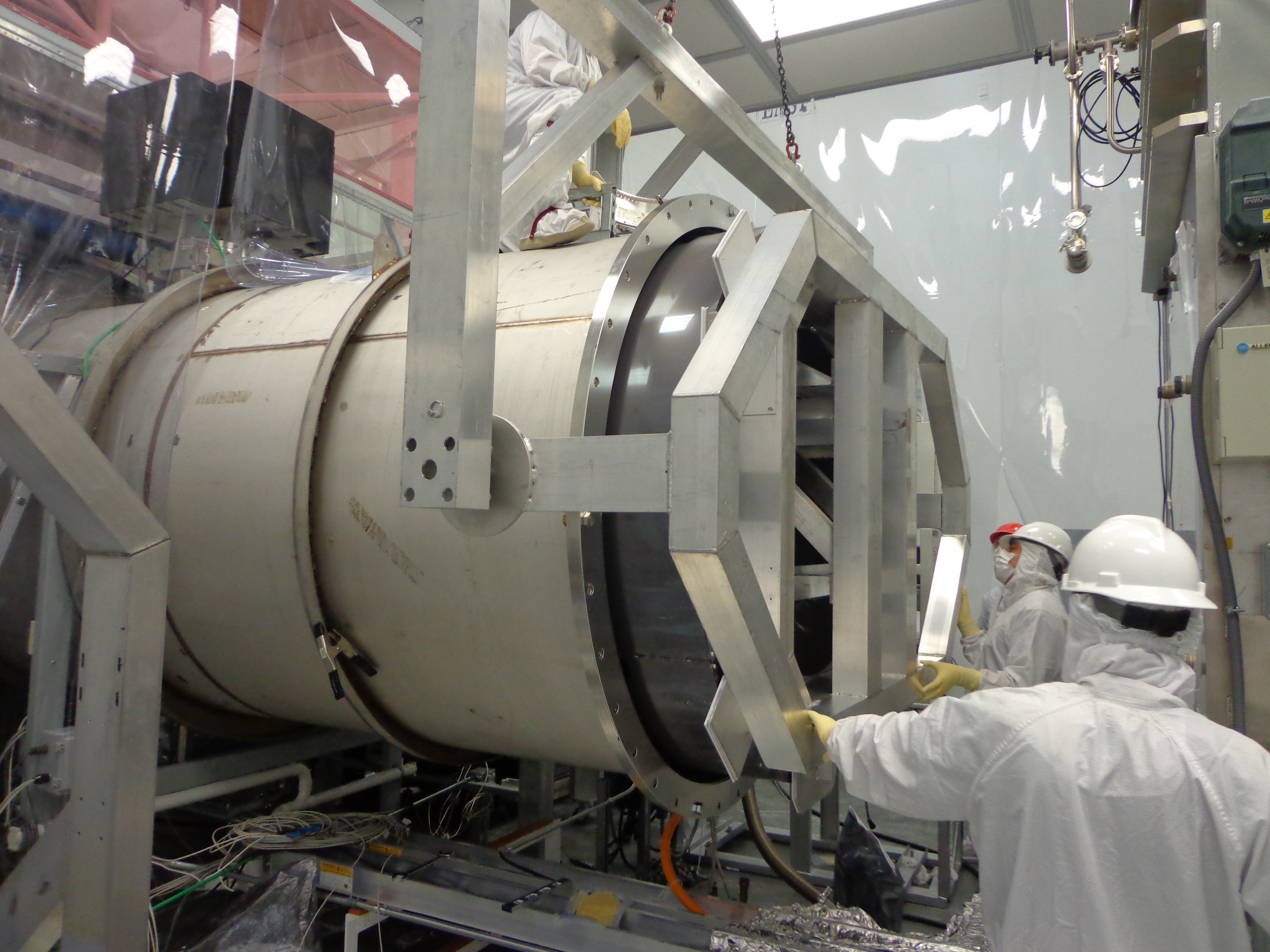
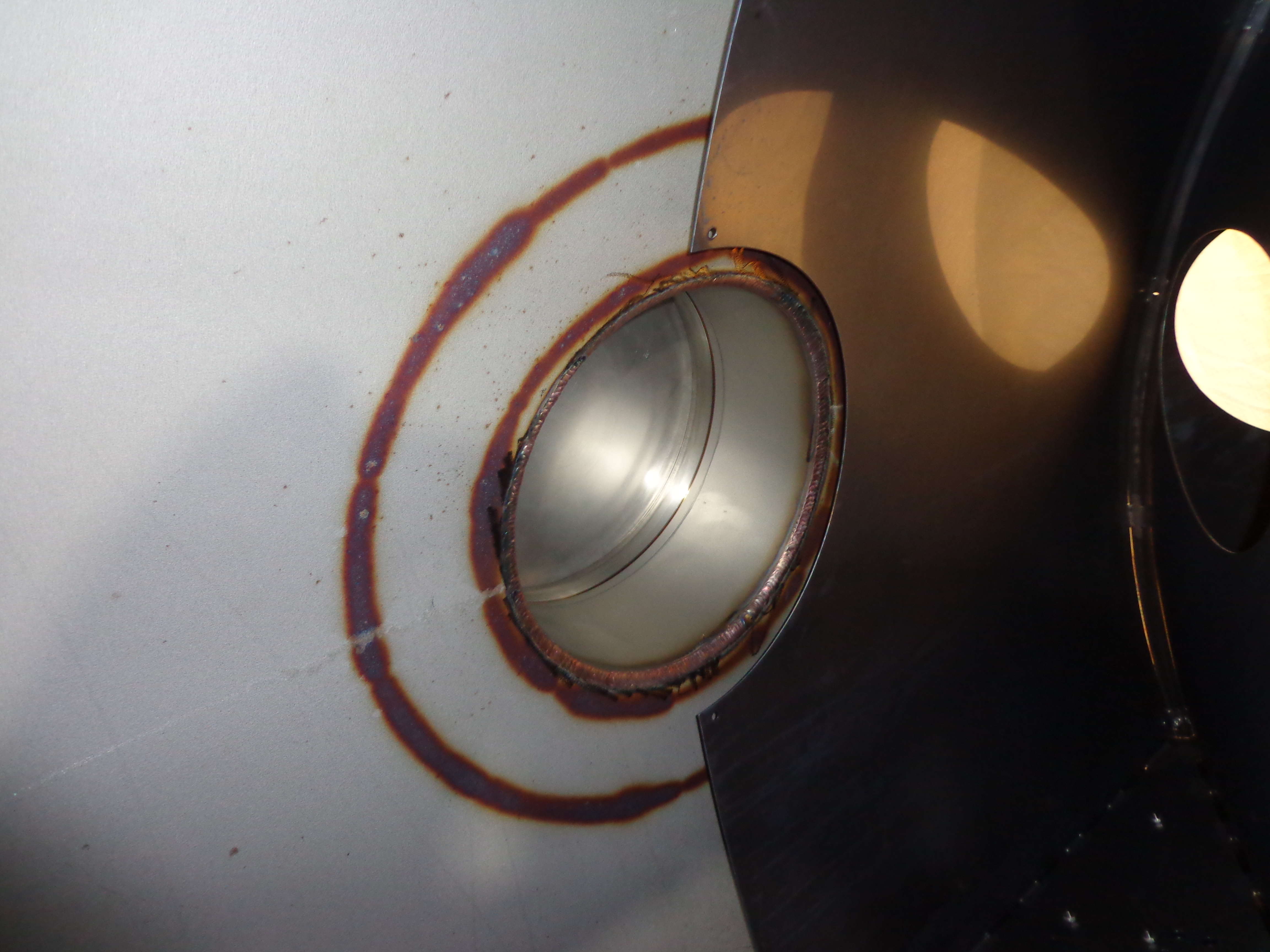
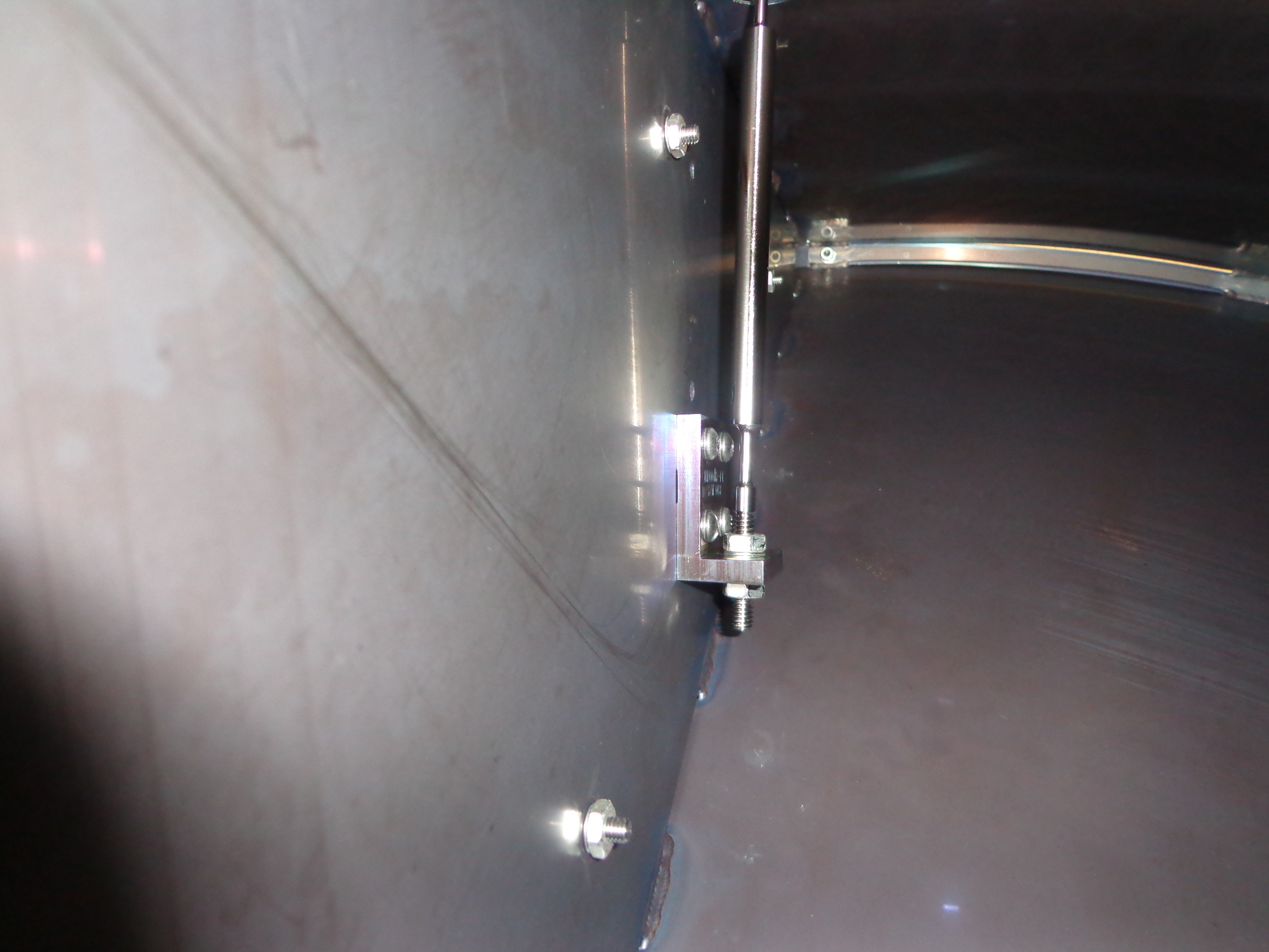
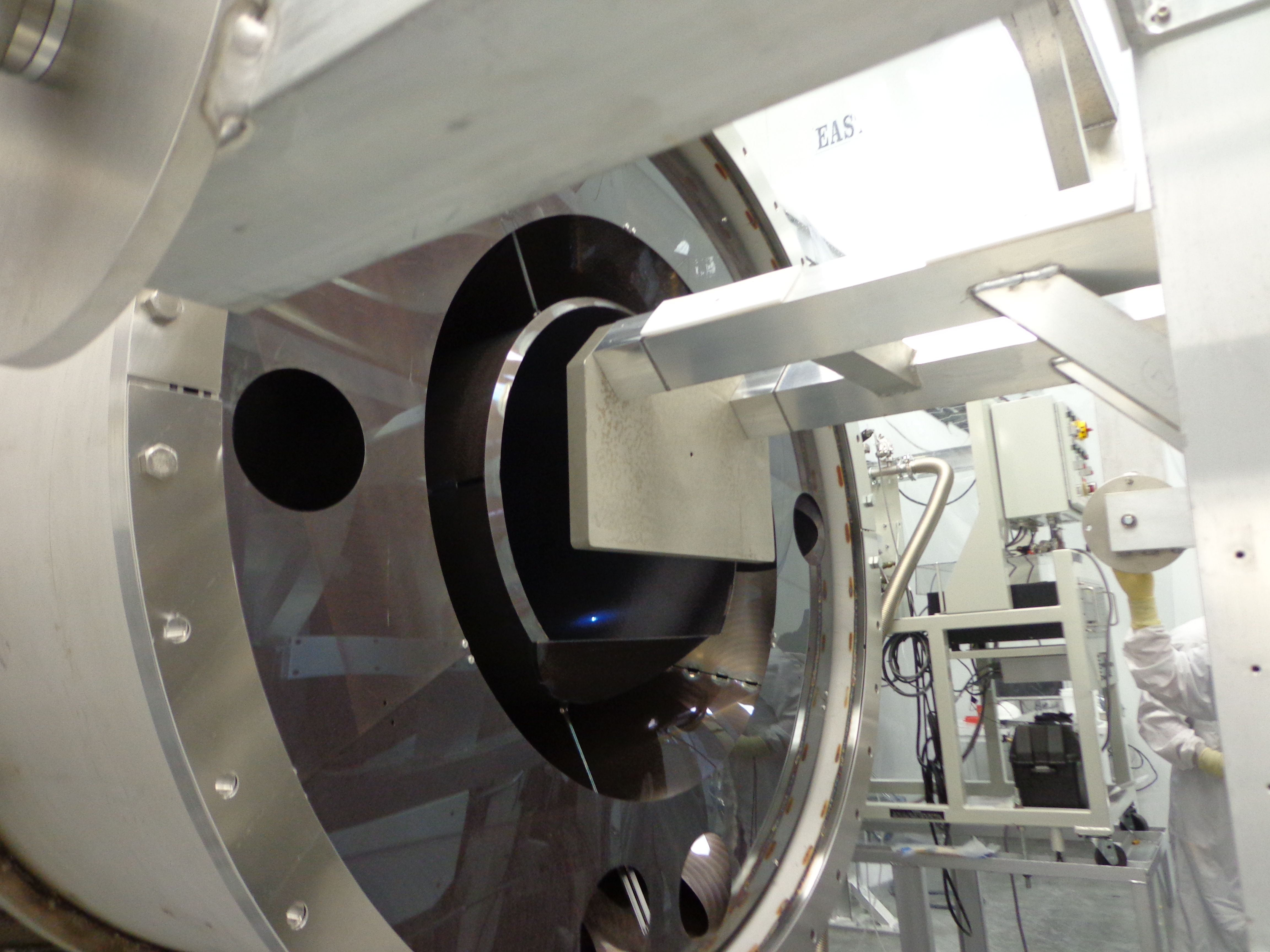
Thursday, 25 July 2013 - The Manifold Cryopump Baffle was installed in H1 End-X!!! (pic 7)

The baffle was lifted and positioned between the Spool and the Gate Valve. It was a tight fit; there were inches of clearance (pic 3). We were stopped once to move the cable trays on the top of the Spool for the Assembly Fixture to insert the Baffle (pic 1 & 2). The Baffle was inserted into the Spool with less than 1 inch clearance around the Baffle (pic 4) and it went in SMOOTH! There were 2 men in chamber. After a few trial attempts to attach the Flexure Rods, the L-Brackets were removed to facilitate the install. Once the Flexure Rods were attached, the Assembly Fixture was removed. One blade released as expected and the z- was set with the Spacing Bar. There was some twist which was corrected at the Flexures. Final measurements to the end of the Spool have the baffle position ~3.25" on the East side and ~3.5" on the West side. Baffle rest 0.5" spacing to the Compression Rings all around. The Copper Plates with o-rings were attached and spacing to magnets set. The cut-out around the Ion Pump (pic 5) looks really good.

The problem of attaching the Flexure Rods will be discussed to see if we can reduce the amount of effort needed for future installs (pic 6).

All photos are available in Resource Space - https://ligoimages.mit.edu/?c=1346&k=434c8ef92c
(Resource Space has pictures of the life of the baffle starting at oxidation, to assembly, ending with installation, but not in any order.)

Many thanks to those who participated in this effort -
Apollo's Bubba, Mark, Randy, Scott & Tyler, Doug Cook, Joe DeRenzis, Jodi Fauver, Gerardo Moreno, Mitchell Robinson, Scott Shankle, Mike Smith, Chris Soike, Calum Torrie, Mike Vargas, Thomas Vo, Nichole Washington, John Worden and the entire Hanford Family!
Images attached to this report