stefan.ballmer@LIGO.ORG - posted 01:04, Thursday 25 July 2013 - last comment - 13:35, Sunday 22 September 2013(7215)
Input Mode Cleaner transmitted frequency noise
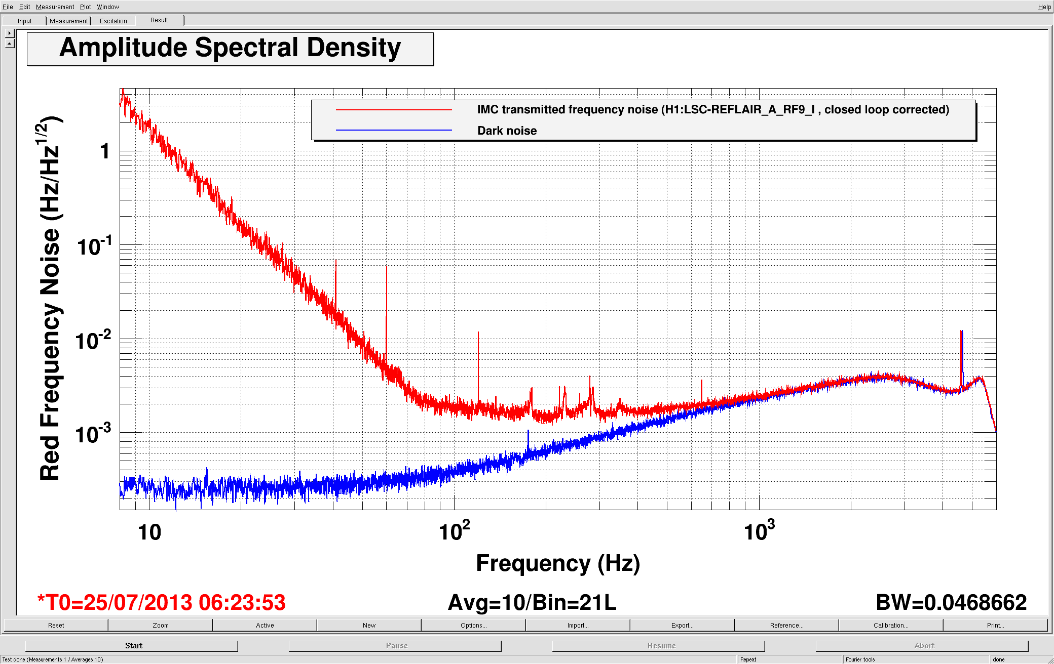
(Jeff, Kiwamu, Stefan)

With the H1:LSC-REFLAIR_A_RF9_I calibrated in Hz, and the open loop transfer function measured, here is the noise it sees: Input Mode Cleaner transmitted frequency noise.
Also plotted is dark noise (shutter closed).

We do not know yet what the ugly noise ~1/f^3 noise is.
Images attached to this report
Comments related to this report
The loop transfer functions are attached:

Open loop gains:
CARM_OLG_RED.txt
CARM_OLG_GREEN.txt

Closed loop gains:
CARM_CLG_RED.txt
CARM_CLG_GREEN.txt

Inverse closed loop gains
CARM_iCLG_RED.txt
CARM_iCLG_GREEN.txt


Inverse closed loop gain with a factor of 1/2 gor Green Hz to Red Hz conversion:
CARM_iCLG_RED_g2r_special.txt
Non-image files attached to this comment

S. Ballmer, J. Kissel

We had made an estimate for the coil driver noise in low-noise mode (State 3, ACQ off, LP ON), and ruled it out. However, I've checked the state of the Binary IO switches, and MC2 is running in State 2, ACQ ON, LP OFF, and and MC1 and MC3 are running in State 1, ACQ OFF, LP OFF. We'll try for this measurement again, with the coil drivers in their lowest-noise mode.
I've plotted the above-attached, red and green, open loop gain transfer functions (see *_full.pdf attachment). Through trial and error, I figured out that the text file columns are (freq [Hz], magnitude [dB], phase [deg]). And remember these are IN1/IN2 measurements, so it's a measurement of - G, not G (which is why the phase margin is between the data and 0 [deg], not -180 [deg]).

Also, because the data points around the UGF were so sparse, I interpolated a 50 point fit around the UGF to get a more precise estimate of the unity crossing and phase margin. See _zoom.pdf for a comparison of the two estimates. I get the following numbers (rounded to the nearest integer) for the raw estimate and the fit estimate:

The raw CARM UGF is: 136 [Hz], with a phase margin of: 33 [deg]
The Fit CARM UGF is: 146 [Hz], with a phase margin of: 30 [deg]
The raw CARM UGF is: 169 [Hz], with a phase margin of: 35 [deg]
The Fit CARM UGF is: 170 [Hz], with a phase margin of: 34 [deg]
Non-image files attached to this comment
