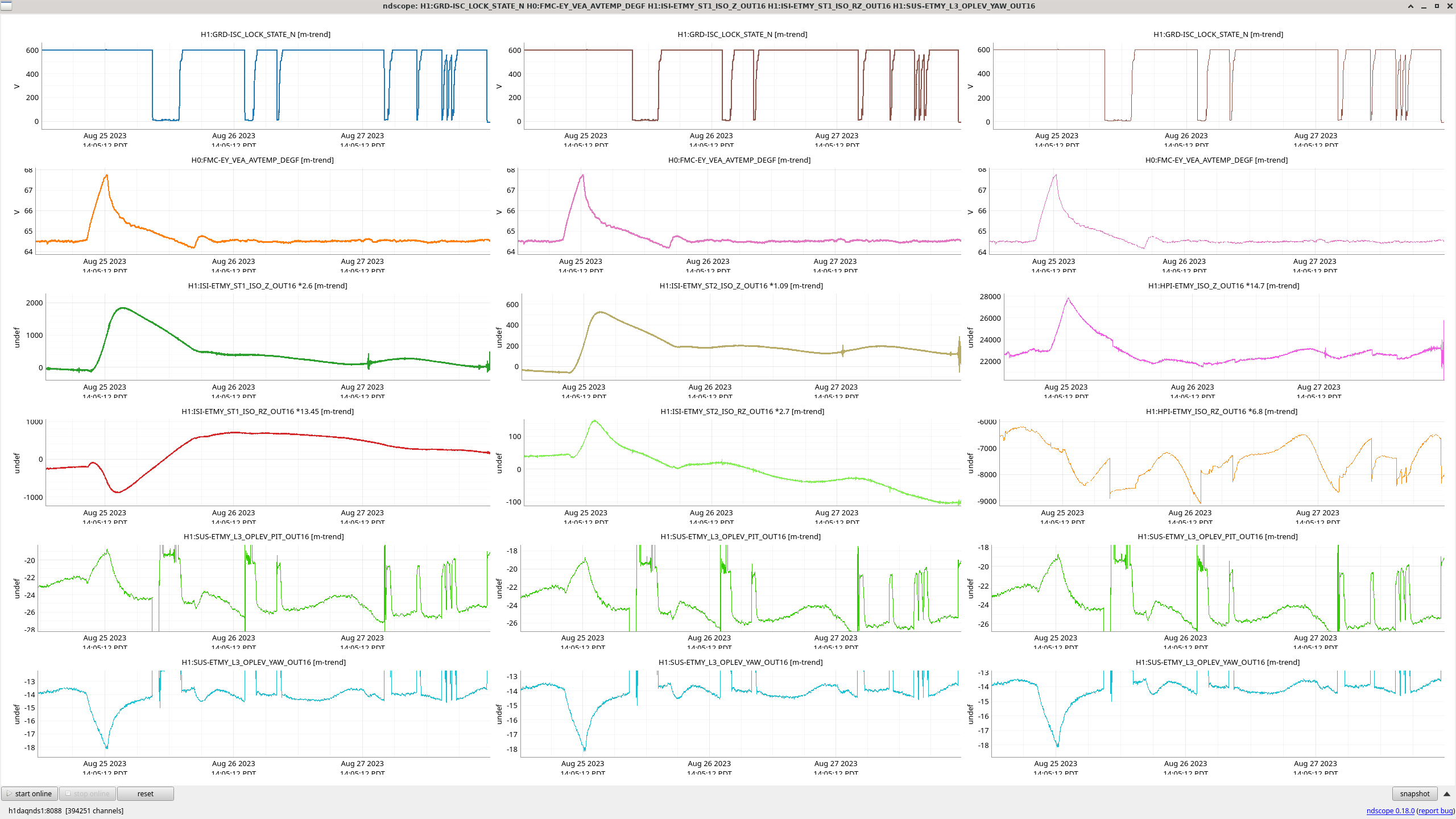
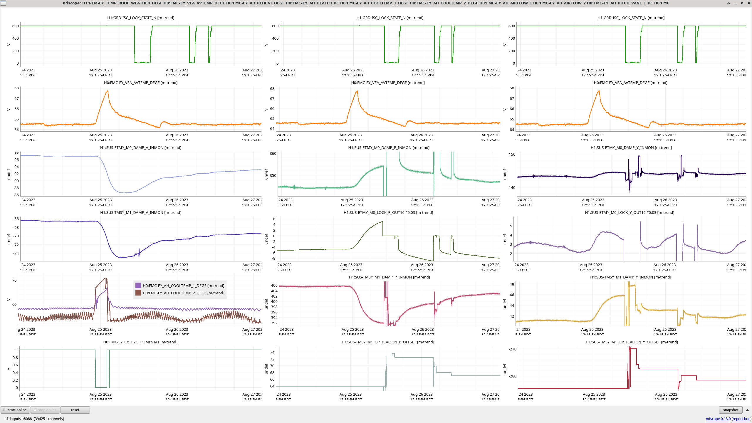
J. Kissel, J. Warner

Given the lovely "natural experiment" of the Aug 25th 2023 ~3.2 [deg F] / 1.8 [deg C]  temperature increase "impulse" over 4 hours at EY (see LHO:72444 and LHO:72428), I wanted to understand both
    (a) How the IFO handles it / what caused the lock loss
    (b) Document the levels and time-scales of alignment change that resulted in bad alignment for *several* lock stretches -- indeed *days* after the impulse.

We often wave our hands saying things like "well, the vacuum system acts like a low pass filter, with a time constant of [[insert hand-waivers favorite time-scale on the order of hours]]." I wanted to see if we could quantify that, and if not, add a bit more clarity to how complicated the situation is.

To do so, I looked at the Y End Stations' signals in Z, RZ, PIT, and YAW that are either
    (1) out of loop, or
    (2) when in-loop -- the loop's feedback control output using the "classic trick" of approximating G/(1+G) ~ 1, where G >> 1, such that (plant) * CTRL = out-of-loop signal as though the loop wasn't there.

Those sensors include
    - HPI ST1 ISO OUT (which are the IPS, under DC-coupled feedback control) -- calibrated into nano- meters or radians
    - ISI ST1 ISO OUT (which are the CPS, under DC-coupled feedback control) -- calibrated into nano-
    - ISI ST2 ISO OUT (which are the CPS, under DC-coupled feedback control) -- calibrated into nano-
    - SUS ETMY M0 LOCK OUT (i.e. the WFS, under DC-coupled global ASC control) -- calibrated into micro- meters or radians
    - SUS ETMY M0 DAMP IN (which are "out-of-loop" because the local damping loops are AC-coupled) -- calibrated into micro-
    - SUS TMSY M1 DAMP IN (equally "out-of-loop")  -- calibrated into micro-
    - ETMY L3 Optical Levers -- calibrated into micro-
(I'm pleasantly surprised at how well they all agree, to the ~0.25 micro- kind of level that I have for these trends.)

I conclude:
    (I) The IFO Yaw is most impacted by the SEI system's RZ motion, due to the Z to RZ cross-coupling of the radially symmetric system of triangular ISI blade springs, as the blades sag from temperature increase
        (i) The total SEI system's yaw swung ~2 [urad] during the excursion dominated by ISI ST1,
        (ii) The SUS ETMY and SUS TMSY follow this input in common, and
        (ii) ISI ST1 takes the longest time to recover alignment --  then trending over *days* slowly back to pre-impulse equilibrium -- and still not yet there as of Aug 28
    (II) The IFO Pitch most impacted by the ETMY and TMSY SUS system's expected Pitch and Vertical sag from temperature increase.
        (i) The IFO's global alignment drives the pitch of ETMY, which drifted *down* in pitch over ~10 [urad] before losing lock, presumably from running out of range
        (ii) The ASC signals seem to slowly drive the ETMY off into-the weeds trying to recover the original, pre-impulse, alignment, causing *eventual* subsequent lock losses as it pushes the optic *past* the pre-impulse alignment position
        (iii) The TMS, which does not have global control, pitches a similar amount, ~14 [urad] in the *opposite direction, up* in pitch, and also taking *days* to get back the original value (somewhat alleviated )
        (iv) The fact that the Sus-point blades are the *same* for the QUAD and TMS, they're the biggest blades in either SUS, and the order of pitching is about the same implies to me that the pitching is dominated by the upper, Sus-point blades.

I attached the trends that drive me towards these conclusions.
Give yourself time -- I've stared at these all afternoon to come to these conclusions. And honestly, I *still* don't think I've looked at enough plots (e.g. I don't show the ETMY alignment sliders that are the operators and/or initial alignment drives trying to make up for the SEI blades yaw and SUS blades pitch).

I also attach a .txt file that goes into more detail about how I calibrated the various CTRL signals, including where I got the transfer function values that are scaling the trends that you see.

Very Interesting!
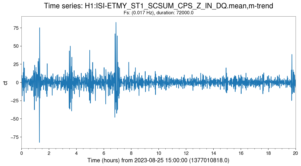
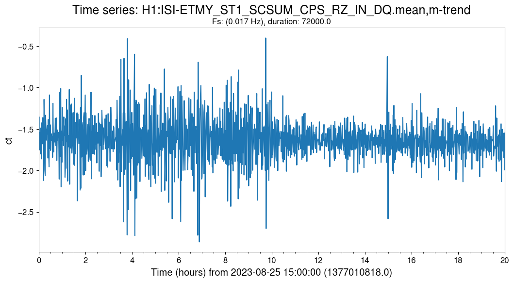
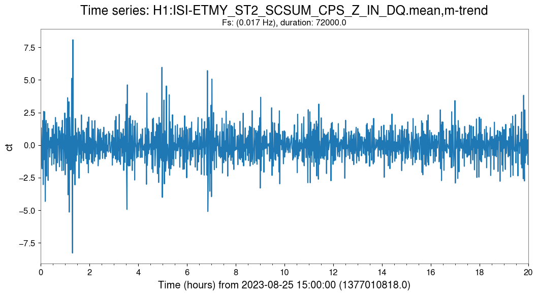
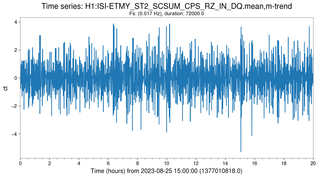
I've added a few more plots which show the in-loop motion as measured by the CPS sensors on ETMY. These show that the platform didn't move down or twist during the temperature excursion. This is what you would expect, given Jeff's plots from above - the springs sag, and the servos compensate. That's all just peachy, so long as there is no yaw seen at the optic - but the oplev does see yaw.
Either - there is some yaw in the ISI which is not seen by the CPS sensor (eg the sensor itself is temperature sensivity - but this should be pretty small) , or
- the yaw is just from SUS, or
- oplev is affected by temperature, or
- the yaw is coming from somewhere else (HEPI, piers, SUS, the devil, etc)
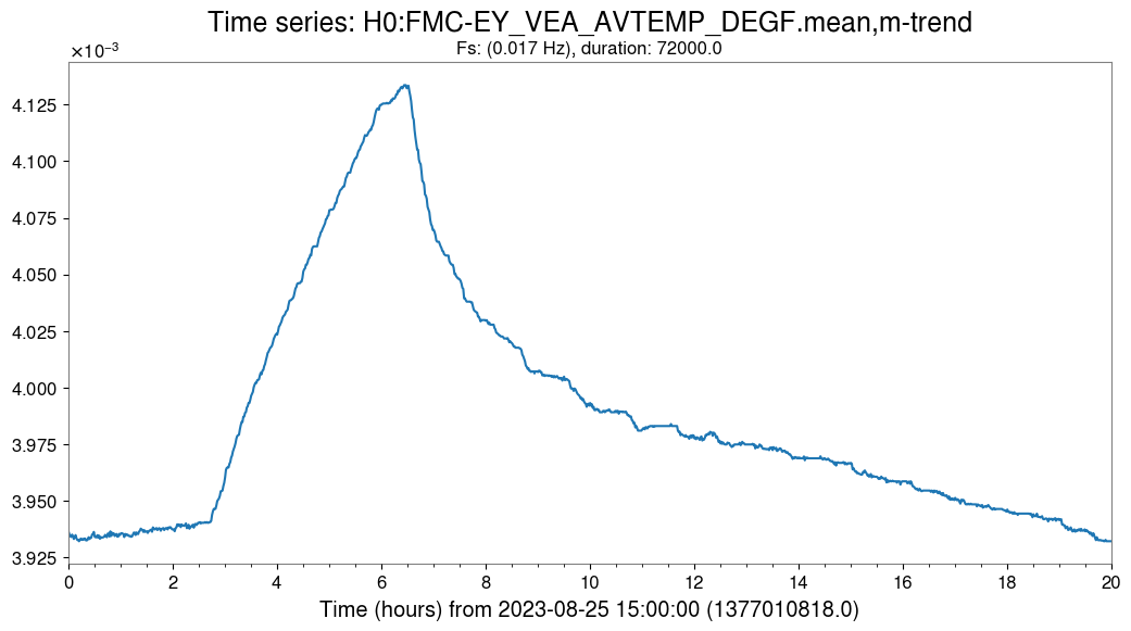
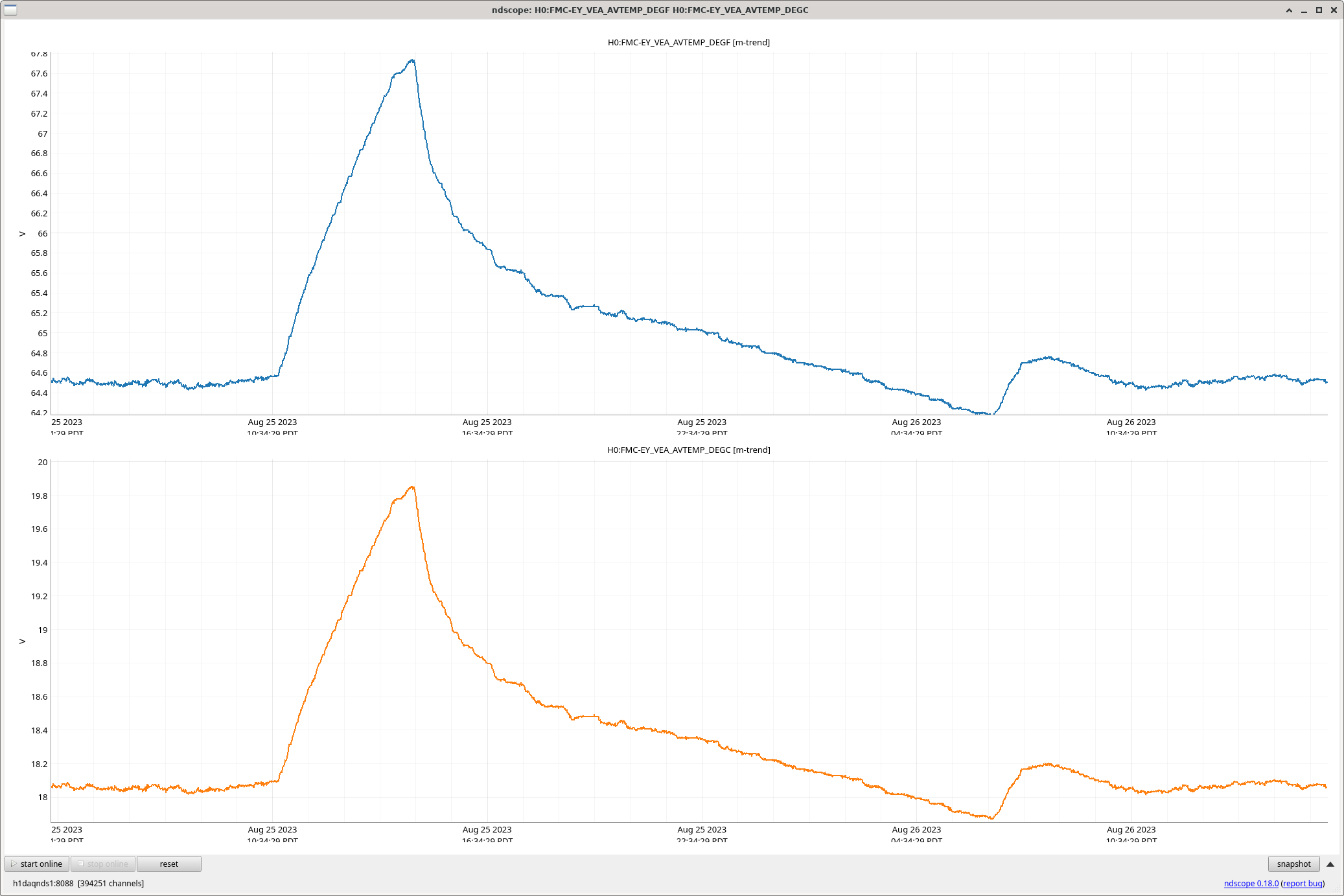
I've not thought about this very hard yet - but I attach a 20 hour time stretch from the temp sensor (calibration is crazy, but the shape matches. not sure what's up) and 4 CPS cart-basis sensor signals (calibration should be nanometers or nanoradians). The in-loop change on the CPS is less than 1 nanorad.