J. Oberling, A. Jennings
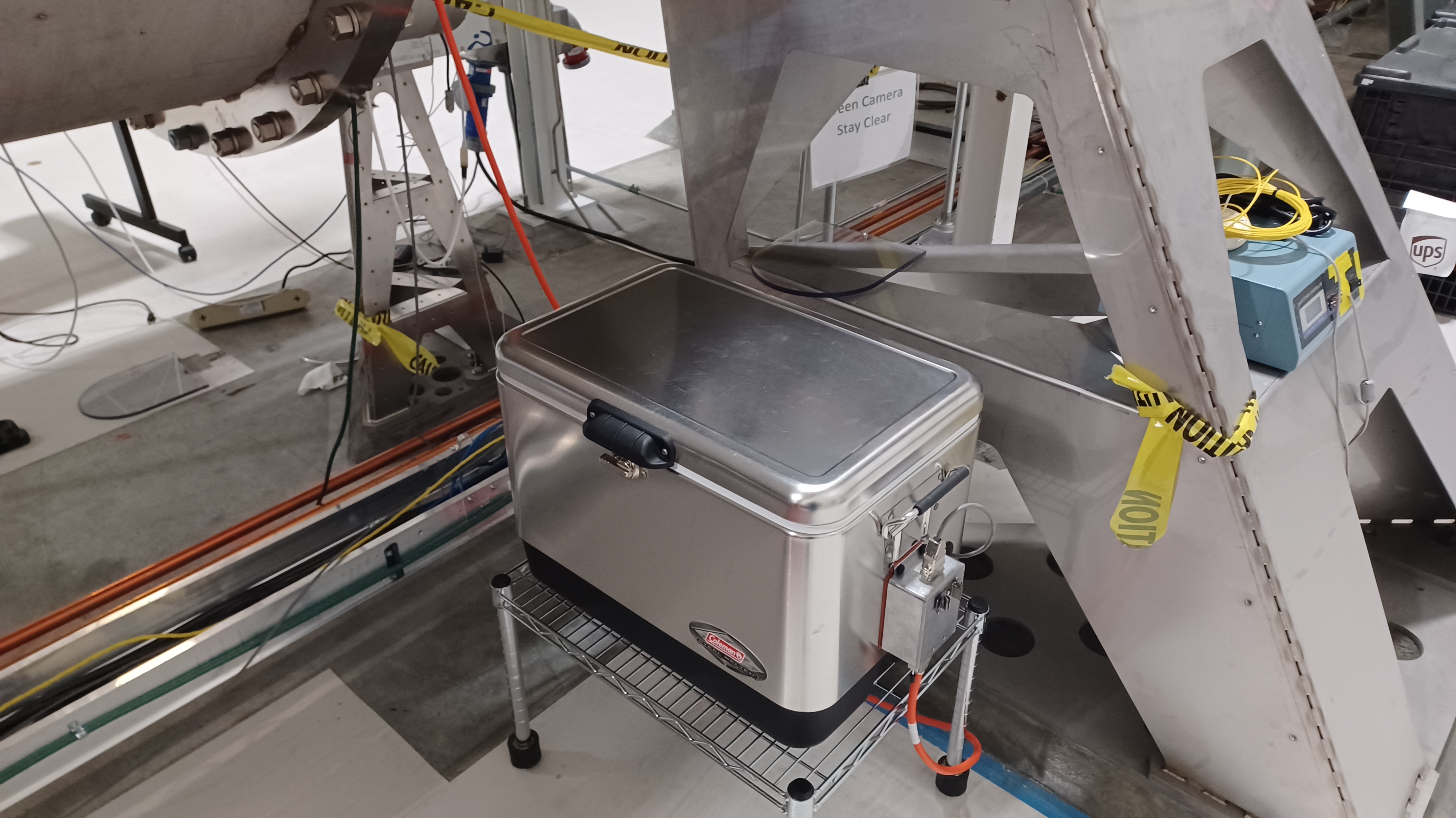
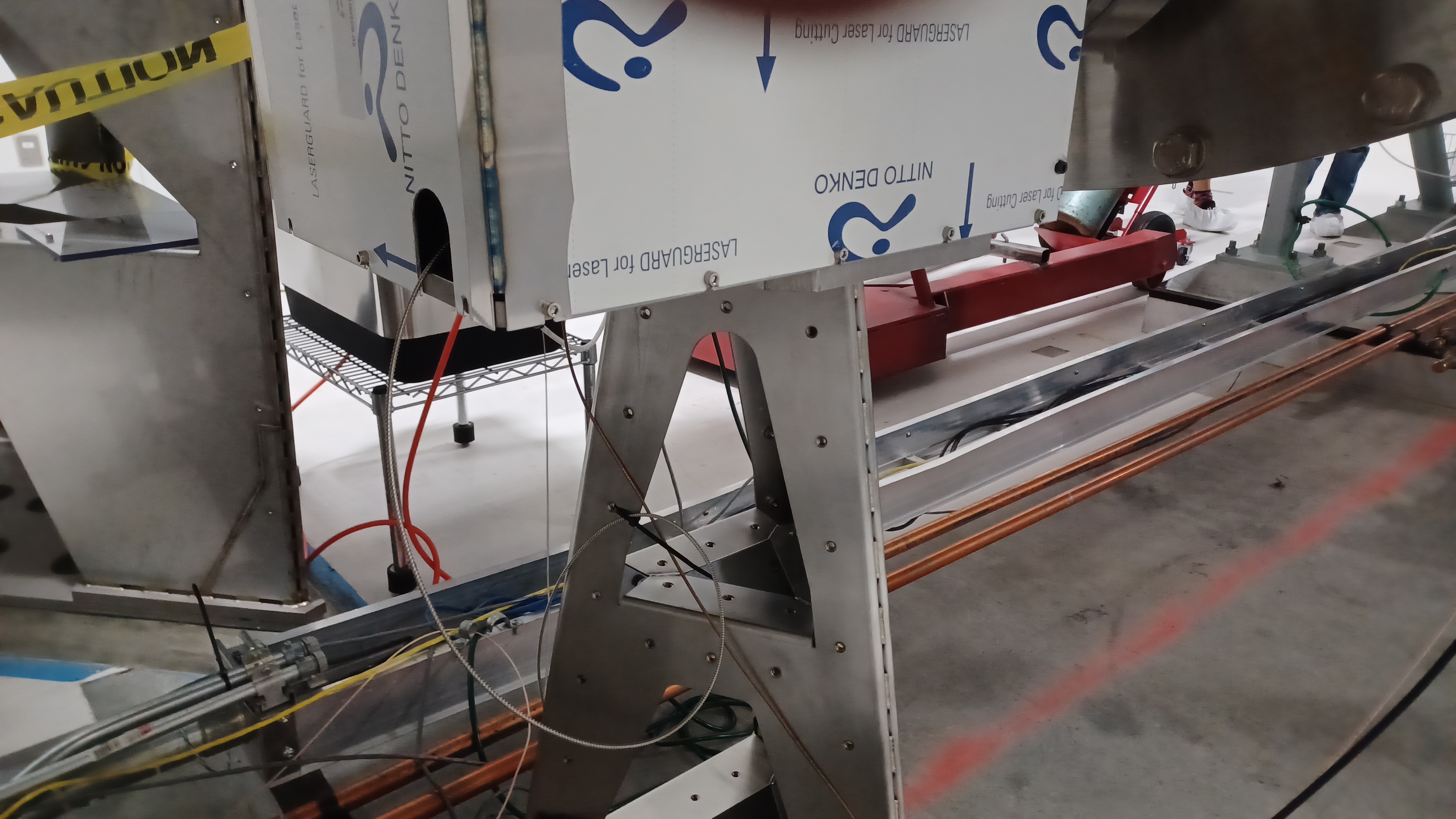
With a relatively light maintenance window and a chance for some extended Laser Hazard time, we finally completed the installation of an old OpLev ECR, FRS 4544. Austin and I removed the existing 10m single-mode fiber and installed a new, 3m armored single-mode fiber, and placed the laser in a "thermal isolation enclosure" (i.e. a Coleman cooler).
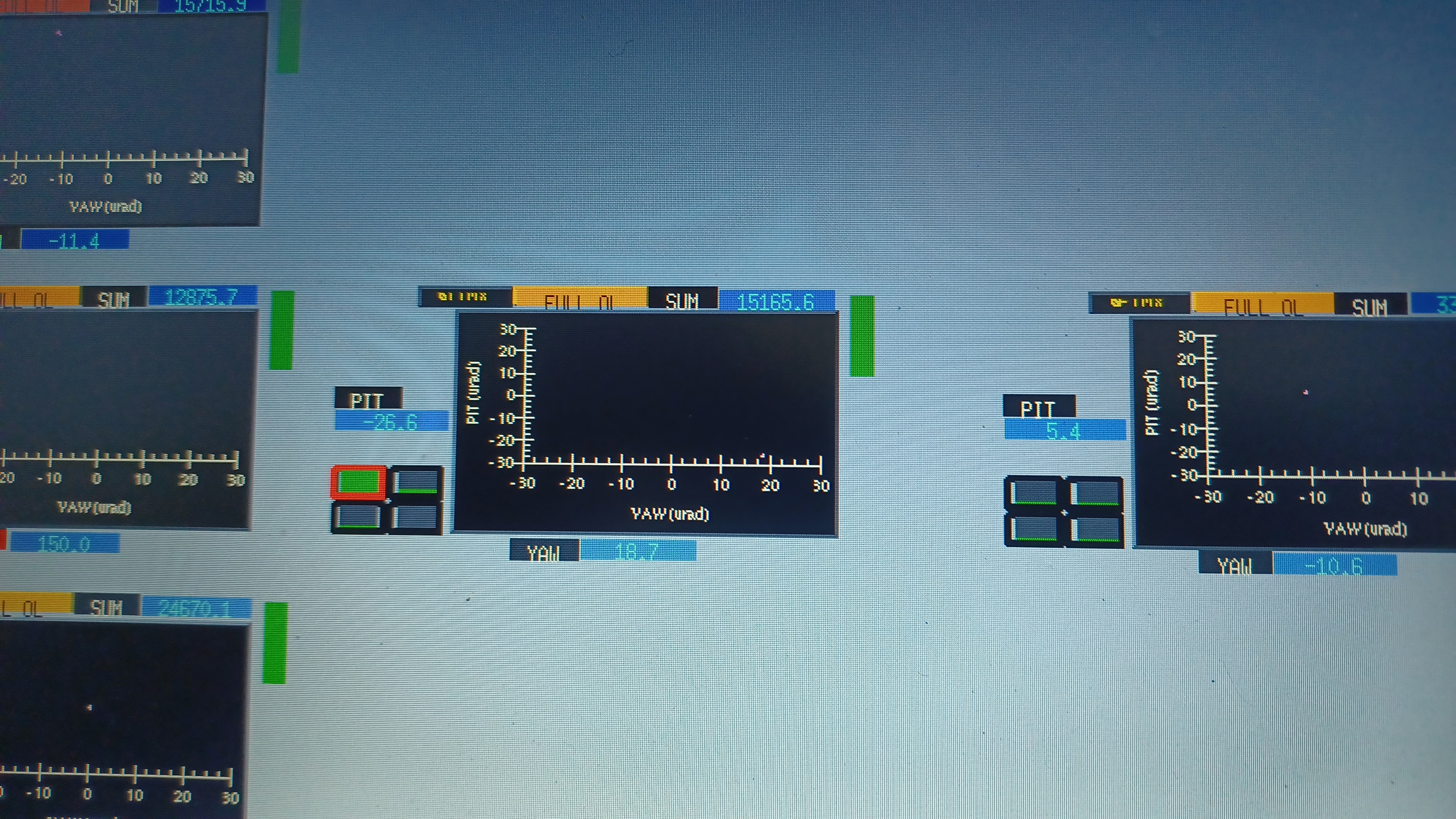
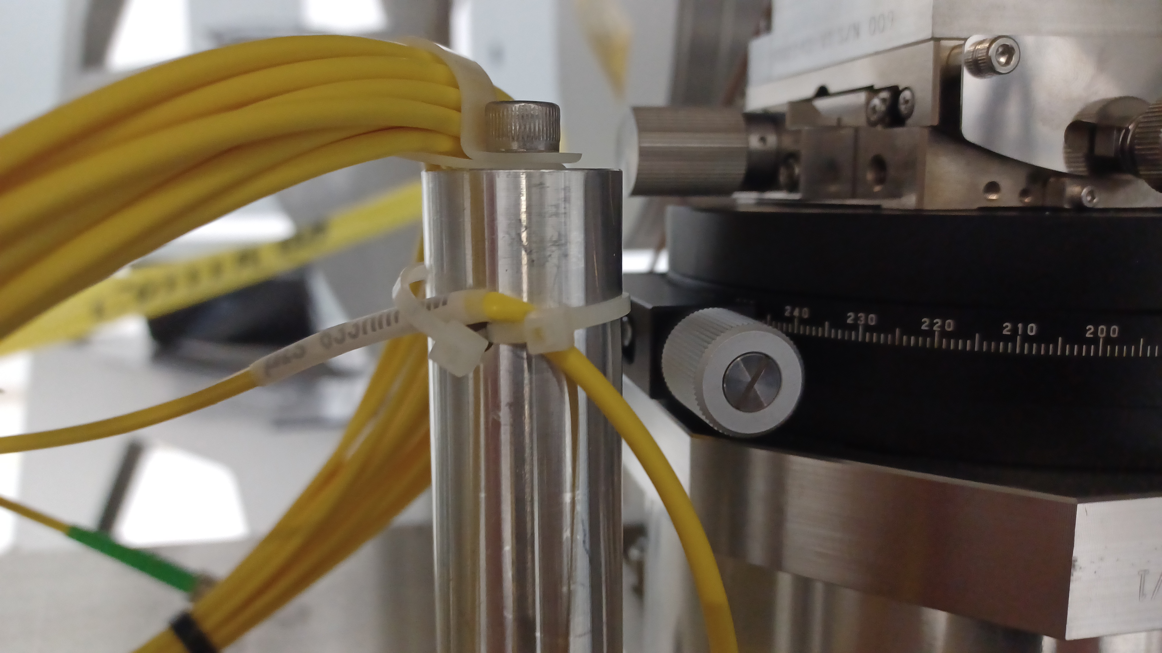
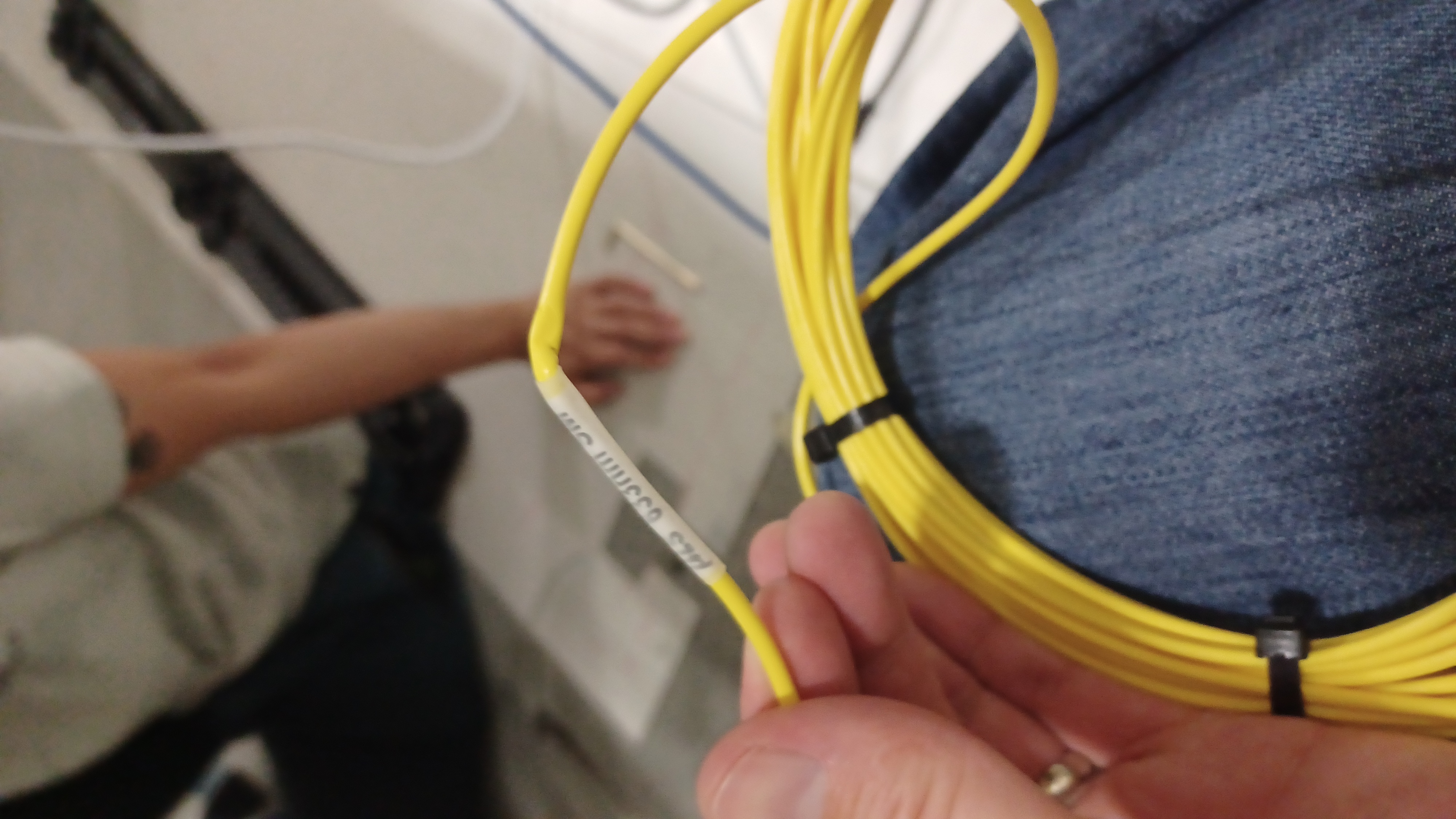
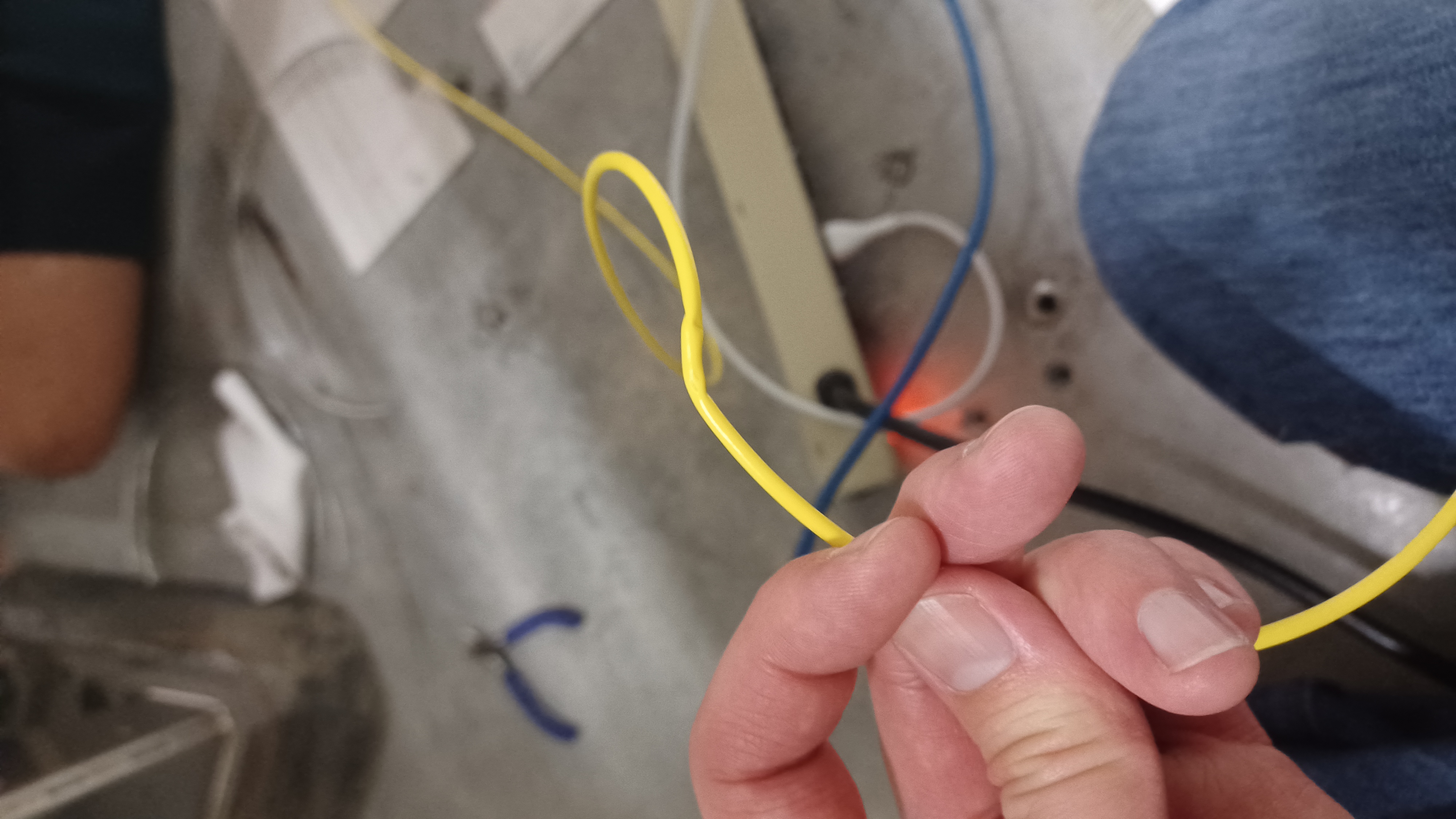
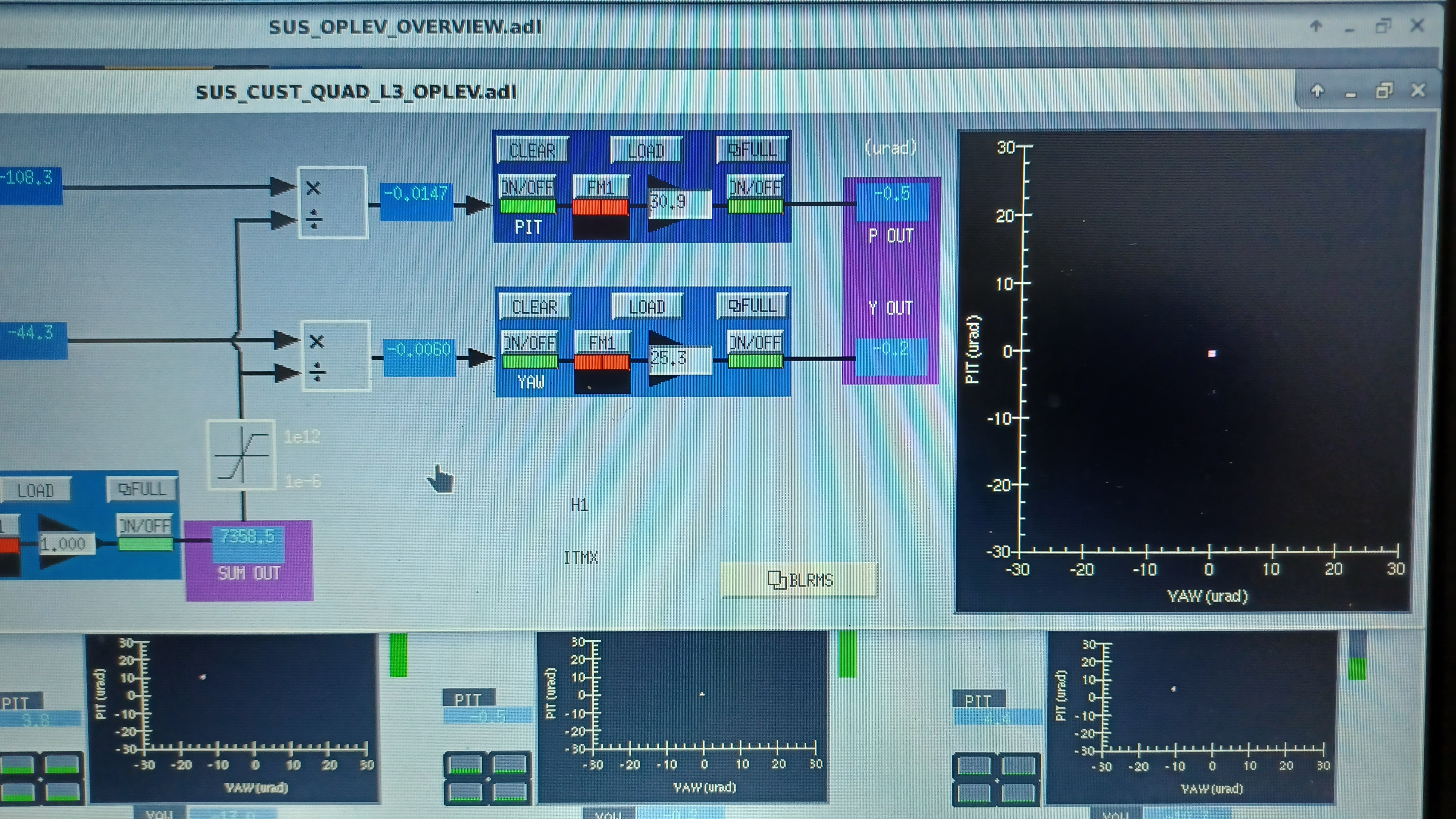
To start, I confirmed that there was power available for the new setup; the OpLev lasers are powered via a DC power supply in the CER. I read no voltage at the cable near the ITMx OpLev, so with Fil's help we traced the cable to its other end, found it unplugged, and plugged it in. I confirmed we had the expected voltage, which we did, so we moved on with the installation. We had to wait for the ITMx front end computer to come back up (had tripped as part of other work), so while we waited Austin completed the transition to Laser Hazard. We took a picture (1st attachment) of the ITMx OpLev data (SUM counts, pitch and yaw readings), then powered down the laser. We placed the laser in the cooler and plugged in the new power supply; laser turned on as expected. We then installed a Lexan viewport cover and removed the cover from the ITMx OpLev transmitter pylon. The old 10m fiber was removed, and we found 2 areas where the fiber had been crushed due to over-zealous strain relief with cable ties (attachments 2-4; this is why we originally moved to armored fibers); I'm honestly somewhat surprised any light was being passed through this fiber. We installed the armored fiber, being careful not to touch the green camera housing and to not overly bend the fiber or jostle the transmitter assembly, and turned on the laser. Unfortunately we had very little signal (~1k SUM counts) at the receiver, and the pitch and yaw readings were pretty different. We very briefly removed the Lexan cover (pulled it out just enough to clear the beam) and the SUM counts jumped up to ~7k; we then put the Lexan back in place; we also tried increasing the laser power, but saw no change in SUM counts (laser already maxed out). This was an indication that we did manage to change the transmitter alignment during the fiber swap, even though we were careful not to jostle anything (it can happen, and it did), and that the Lexan cover greatly changes the beam alignment. So we loosened the locking screws for the pitch and yaw adjustments and very carefully adjusted the pitch and yaw of the launcher to increase the SUM counts (which also had the effect of centering the beam on the receiver). The most we could get was ~8.3k SUM counts with the Lexan briefly removed, which then dropped to ~7k once we re-installed the transmitter cover and completely removed the Lexan (no viewport exposure with the transmitter cover re-installed). We made sure not to bump anything when re-installing the transmitter cover, yet the SUM counts dropped and the alignment changed (the pitch/yaw readings changed, mostly yaw by ~10 µrad). Maybe this pylon is little more loose than the others? That's a WAG, as the pylon seems pretty secure.
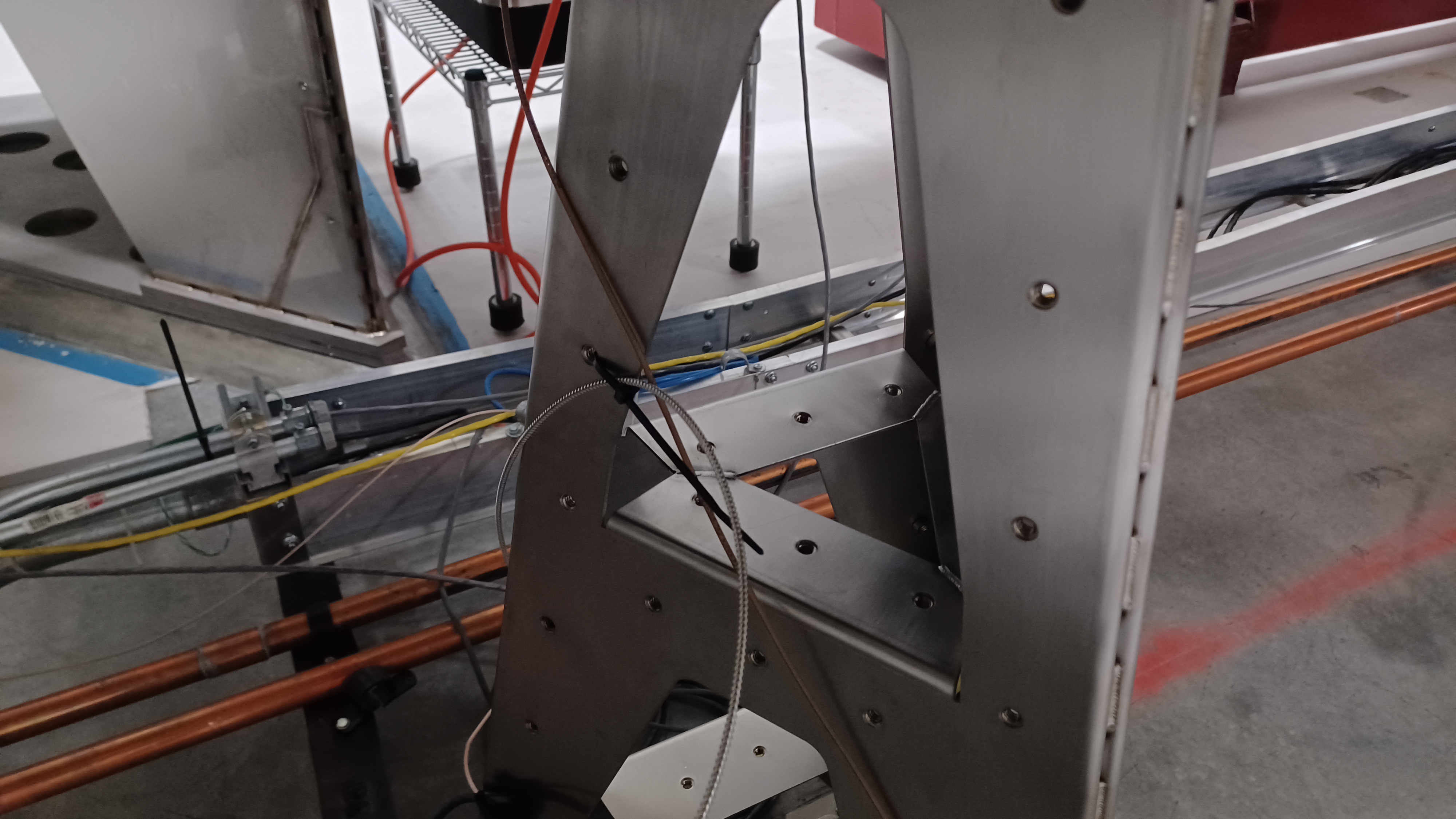
I can't explain why the SUM counts are so much lower; could be the difference between the new and old fibers, we could have really changed the alignment so we're now catching a ghost beam (but I doubt this, we barely moved anything). Honestly I'm a little stumped. Given more time on a future maintenance day we could remove the receiver cover and check the beam at the QPD, but as of now we have what appears to be a good signal that responds to pitch and yaw alignment changes, so we moved on. We re-centered the receiver QPD, and now have the readings shown in the 5th attachment; ITMx did not move, it stayed in its Aligned state the entire time. This is all the result of our work on the OpLev. We'll keep an eye on this OpLev over the coming days, especially watching the SUM counts and pitch/yaw readings (looking for drift and making sure the laser is happy in its new home; it is the oldest installed OpLev laser at the moment). The last few attachments are pictures of the new cooler and the fiber run into the transmitter assembly. This completes LHO WP 11422 and FRS 4544.
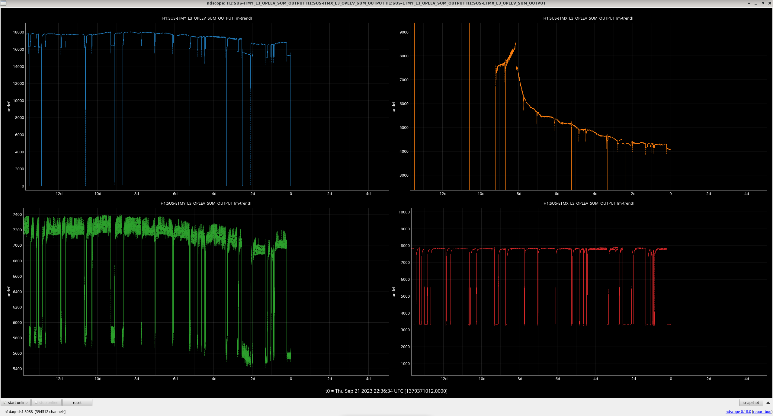
The ITMX OPLEV sum has been dropping past one week. It was around 7000 counts last week and since then it has gone down to around 4000 counts - please see screenshot attached.