Fil, Dave, Rahul
Turns out that the fault reported by Jenne (see alog 73447) at the ETMY R0 Test Coil Enable (which went red) was due to a faulty cable connecting Binary Input to the Binary Card in the IO chassis. It took us 3hrs to figure it out after checking the IO chassis and Coil driver - which were working fine. Dave also power cycled the IO chassis to help us figure it out. Fil thought it could be the binary card (at first and IO chassis later) which we replaced (only the binary card - GCRBS96004326) with a new one but no success. In the end we changed the cable and it made the Test coil (channel F1 and F2) working again.
WP 11477 Closed.
D1002741 - aLIGO SUS ETM System Wiring Diagram
D1001782 - aLIGO Production Quad Top Coil Driver Chassis
D1001269 - aLIGO Binary Input Interface Chassis (4xDB9, 2xDB37 version) Top Assembly
MEDM and wiring diagram don’t match. Following D1002741 we traced the faulty channel of RO FC1 to Quad Driver Chassis in SUS-C1, U39. This chassis corresponds to RO channels:
1. RO FC1
2. RO FC2
3. RO FC3
4. RO SD
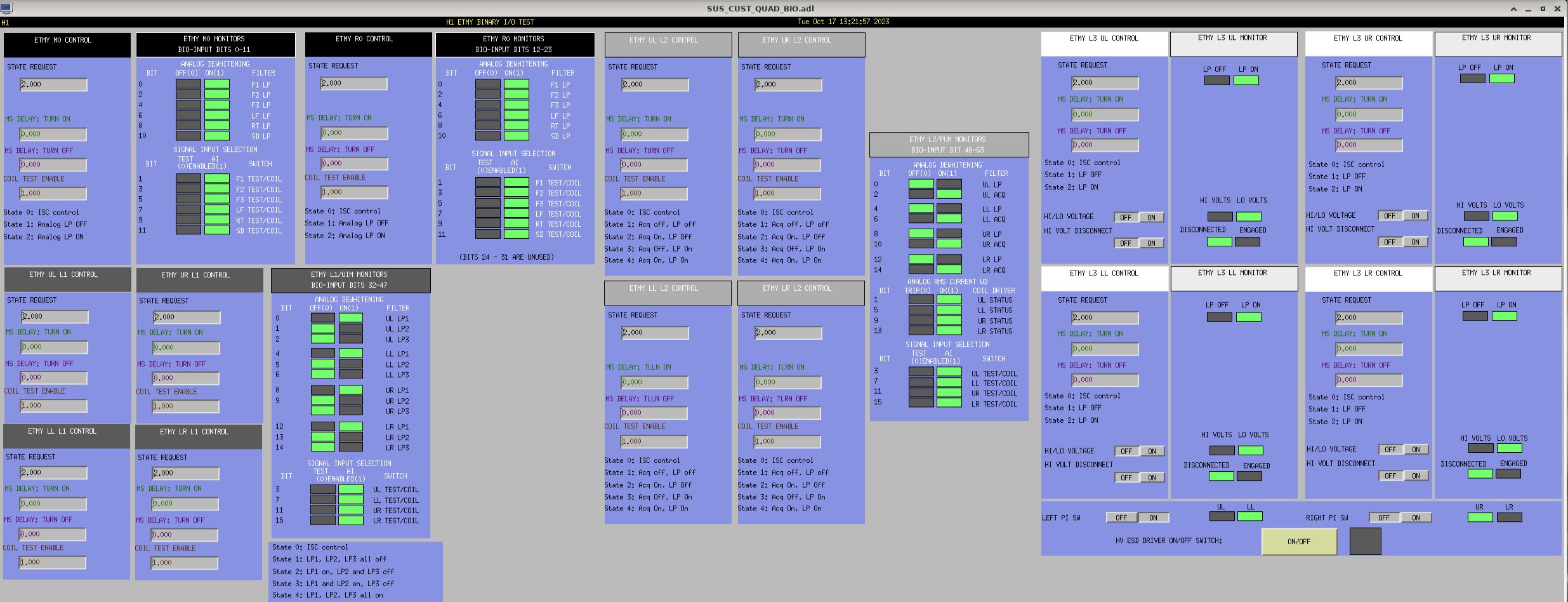
Readback channels are connected from the quad driver chassis to the binary input chassis (SUS-C1, U18, Port 3, CH16-23). A DB37 to DB9 cable is used. We disconnected the cable on the binary input chassis and injected signals. We saw a response in the medm in the following order:
1. MO RT
2. MO SD
3. RO FC1
4. RO FC2
We expected a response on the RO FC1/FC2/FC3/SD channels.