References: alog 73706, 73367
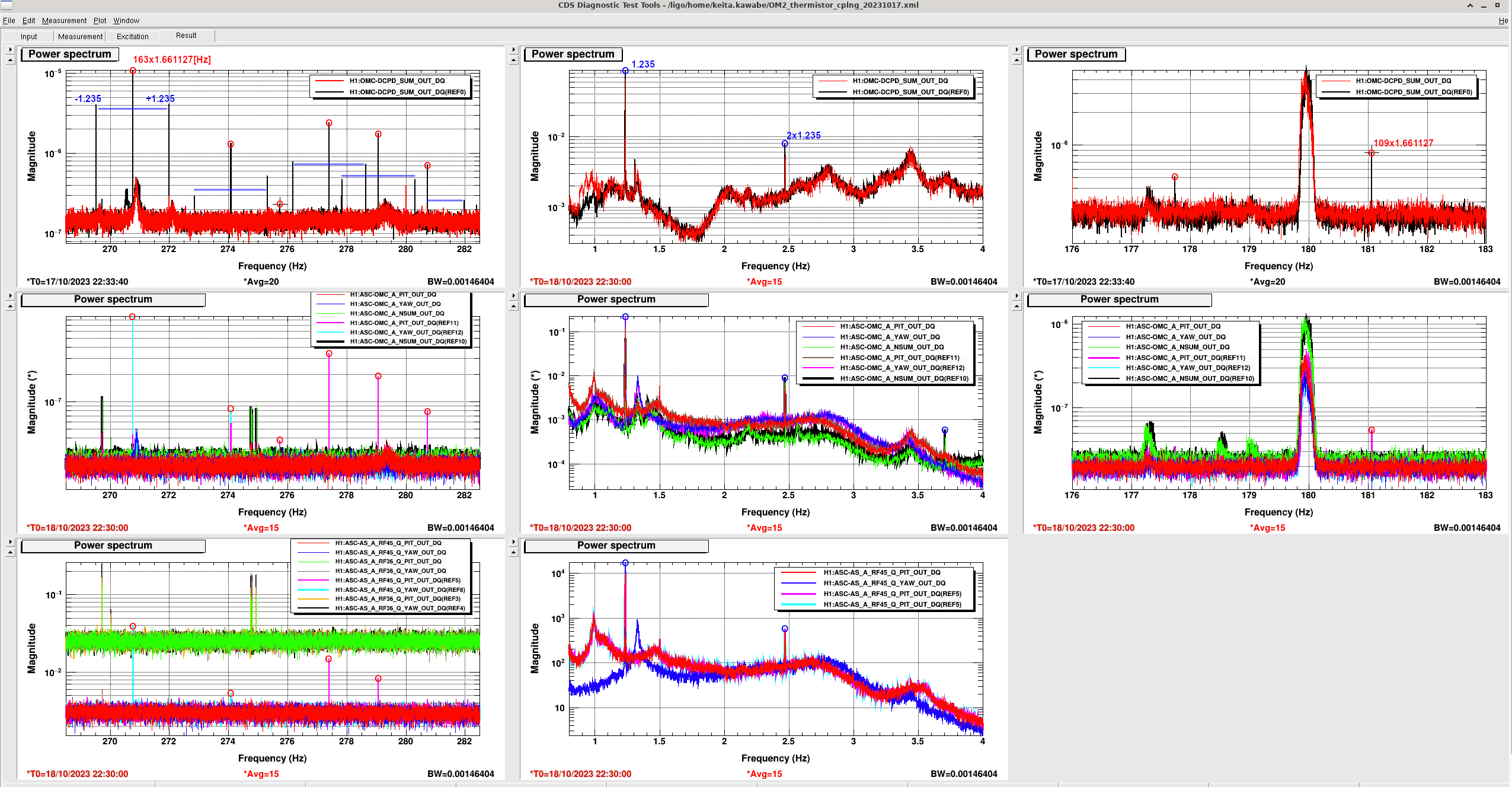
Attached is the comparison of Oct/18/2023 22:30 UTC (current traces, no comb, thermistors cut off from Beckhoff but the heater is still driven by Beckhoff) and Oct/17/2023 22:33:40 (references, with 1.66Hz comb plus 1.235Hz SB to the 1.66Hz comb, thermistors and the heater connected to Beckhoff).
Red circles show 1.66Hz harmonics while blue ones show 1.235Hz harmonics or 1.235Hz SB to the 1.66Hz comb.
1.66Hz comb is visible in OMC QPDs (middle row, though only A is shown here, B is similar) at around 270-280 Hz as well as 177-180Hz, but only in PIT and YAW and NOT in NSUM (which I normalized by the DC value). This strongly suggests that this is either alignment or mode shape change.
We don't see anything at the fundamental 1.66Hz though, maybe the SNR is not enough. OTOH 1.235Hz appears in the current traces as well as references in the middle column. I haven't observed anything like 1.235Hz on the floor in Beckhoff, so I assume that this is NOT from the Beckhoff heater driver DAC. It's unclear if 1.235Hz is length-like (i.e. AM) signal coming from the IFO or if it's also alignment/modal shape change as the signal appears in PIT, YAW and NSUM.
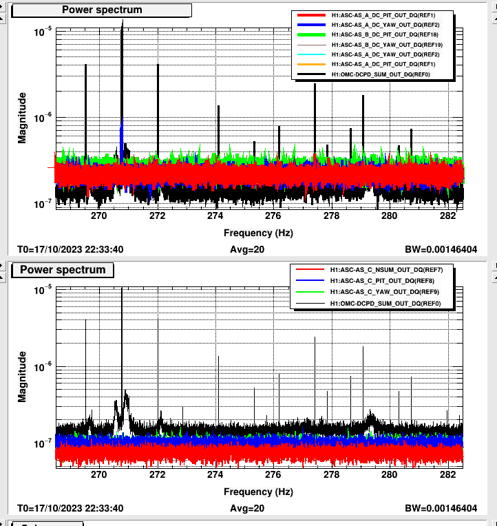
In the second attachment, ASC-AS_A and AS_B DC don't see much except AS_A_DC_YAW sees something at 270.76Hz (top blue). The light power on these should be similar to OMC QPDs but WFS DC doesn't have the ISC whitening filter. ASC-AS_C doesn't see anything (2nd attachment bottom). This is what as AS_C is upstream of OM2 and the imprinting of the noise via the DARM loop shouldn't be strong at 270-280Hz, but note that it only receives 10 times smaller power than OMC QPDs, so the SNR is not as good anyway.
To measure the coupling TF from thermistor current to DARM, I'll route OMCD-DCPD_TEST_EXC to one of the thermistors (hot one at first, as it's mounted on the thermal compression ring which is closer to the electrical loop formed by the heater circuit).
(Sheila mentioned that when OM2 heater was off while the full connection to Beckhoff was still maintained, we didn't see the comb even though 1.66Hz thermistor switching should have been going on. It could be a magnetic coupling (e.g. the single loop electric circuit formed around the compression plate by the heater and its wires generates magnetic field that will push floppy thermistor wires that carry 1.66Hz current?) or maybe dependent on the tightness of the compression ring itself. We can easily distinguish the two by injecting into thermistors and turn off the heating . If the coupling change is instantaneous, it's probably the magnetic field.)
During the maintenance, I disconnected the H1:OMC-TEST_DCPD_EXC Lemo cable from the dual DB9 breakout panel in ISC R5 by HAM6 (so that it won't injected into the DCPD whitening), and used the TNC connector above LEMO to reroute the signal to the Thermistor 2 input at the back of the OM2 heater driver.
I used the breakout board at the back of the OM2 heater driver chassis as follows:
pin 9&11 (Thermistor 2 pin A and B) -> positive out (center conductor of TNC) of H1:OMC-TEST_DCPD_EXC.
pin 22&24 (Thermistor 2 pin C and D) -> negative out (isolated shell of TNC) of H1:OMC-TEST_DCPD_EXC.
pin 10&12 (Thermistor 1 pin A and B) -> bundled together on the breakout board but not connected to anywhere else.
pin 23&25 (Thermistor 1 pin C and D) -> bundled together on the breakout board but not connected to anywhere else.
pin 6&19 (Heater Driver voltage input) -> Beckhoff driver voltage.
(Before connecting it to the thermistors, I roughly measured the voltage across the H1:OMC-TEST_DCPD_EXC pins using a scope on a battery and it had ~15mV DC and maybe 5 to 10mV RMS.)
Max power rating of the thermistor is 18mW at 25C, it's substantially hotter than 25C for Thermistor 2, so I'll make sure NOT to exceed 5mW or so out of caution. Thermistor 2 resistance is more than 4kOhm but less than 5k when hot, so the maximum voltage would be something like sqrt(5mW*4kOhm)~4.5VRMS or ~12Vpp.
I didn't have time to do any measurement today so I'll use commissioning window.