As was briefly mentioned in alogs 73853 and 73917, I injected into thermistor 2 (hot one which is directly mounted on the compression ring of the OM2 mirror) and thermistor 1 (cold one mounted on the back of the T-SAMS structure) independently, and measured the transfer fucntion from the injection to DCPD-SUM (and some other TFs).
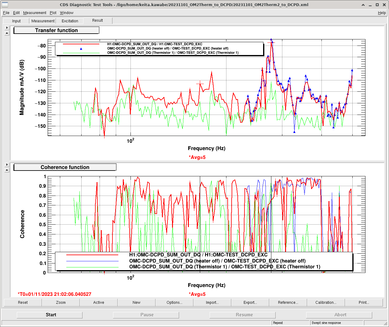
All traces in the attached show the transfer function and coherence from OMC-TEST_EXC (calibrated to the voltage across the Thermistor) and DCPD_SUM (in mA) when H1 is in high power. Red is the injection into Thermistor 2 (hot one), green is into Thermistor 1 (cold one), both while the heater was ON. There are many peaks, most notably the one centered at around 277Hz (that's where CW people observed the most problematic comb structure) but there are others like 78, 93, 105, 144, 154, 166, 314 and 356Hz with good coherence.
The coupling is actually very small for broadband noise, it's only problematic for lines like we've experienced. For example, even if we take the peak at 277Hz (-75dB = 1.8E-4 mA/V) for Thermistor 2, in order for the voltage noise to be comparable to e.g. the shot noise for 40mA DC (~1.1E-7 mA/sqrtHz), the voltage noise should be ~600uV/sqrtHz (because 1.1E-7 [mA/sqrtHz] / 1.8E-4 [mA/V]) at 277Hz, which is a big number.
Thermistor 1 TF amplitude is smaller by more than 30dB than Thermistor 2 measured at around the 277Hz peak. This cannot be explained by the current difference due to lower resistance of the hotter thermistor (thermistor 1 is 7.41k, thermistor 2 is 4.08k, measured on the floor). It should be the location of the thermistor. FYI Thermistor 2 is mounted on the compression ring of the T-SAMS and is therefore much closer to the mirror than Thermistor 1 that is mounted on the back.
Within the resolution of this measurement, frequencies of Thermistor 1 peaks that are visible do match with Thermistor 2, but the resolution is not great (~2Hz at around 277Hz) so it's not clear if we're looking at the same resonance driven by different thermistors, or if this is actually two different resonances, each belonging to one thermistor but not the other.
Blue is the injection into Thermistor 2, but this time the measurement was done immediately after the heater was turned OFF. I only measured down to 220Hz or so, but anyway I see no real difference between the blue and the red. This means that the magnetic field formed by the heater loop around the mirror is NOT relevant for the coupling. Since our experience was that the comb was NOT there while the OM2 was cold, maybe the coupling is dependent on the tightness of the compression ring.
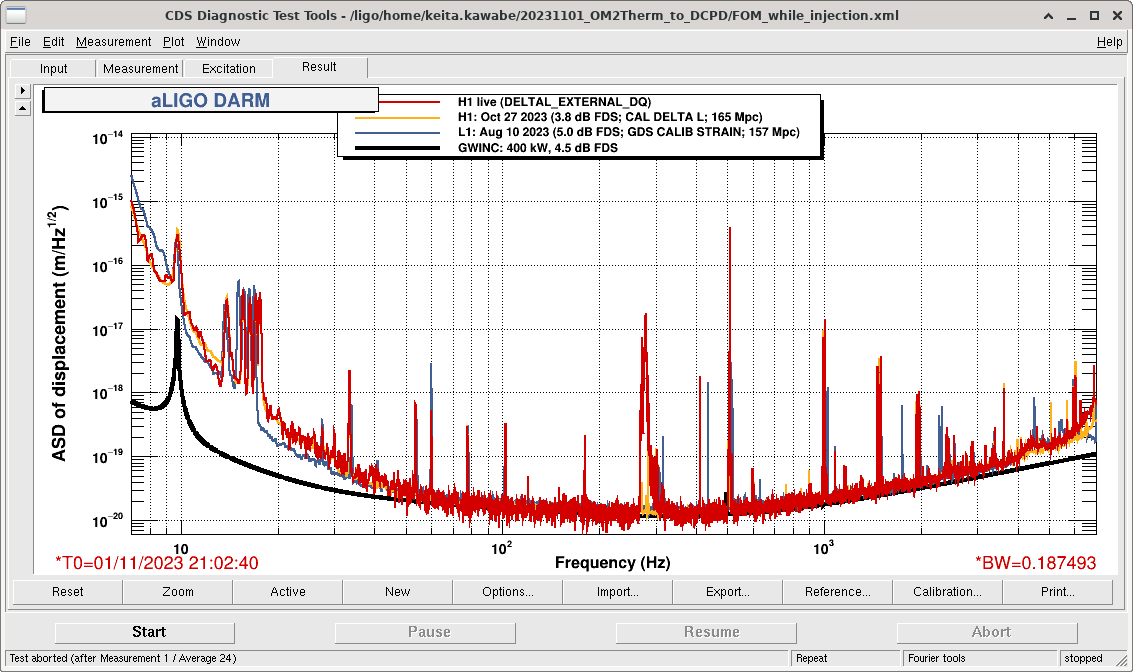
Injection amplitude was constant (A=8000 i.e. 16000cts pp sine wave for all frequencies, corresponding to ~4.9Vpp across the thermistor), and I was making huge lines in DARM (2nd attachment).
After the measurement, all breakout boards and temporary cables and handheld voltage reference and things were disconnected from the system (but were left on the work table by HAM6, I'll pick them up during the next maintenance). EXC cable was connected back to the DCPD whitening, and Beckhoff cable was connected back to the OM2 heater driver.
Do you see the responce in the DCPDs without the light i.e. is the coupling purely electric ?
No, without any light on the DCPD there were no lines on it.
We also tested direct coupling into the OMC PZT by putting the OMC half off the fringe using a direct laser beam. No signal as well.