jeffrey.kissel@LIGO.ORG - posted 19:16, Friday 03 November 2023 - last comment - 14:23, Tuesday 07 November 2023(73976)
PSL Frequency Noise as measured by IMC down to 0.01 Hz; Two IFO Configs and Compared with ISI GS13 Projection of CARM
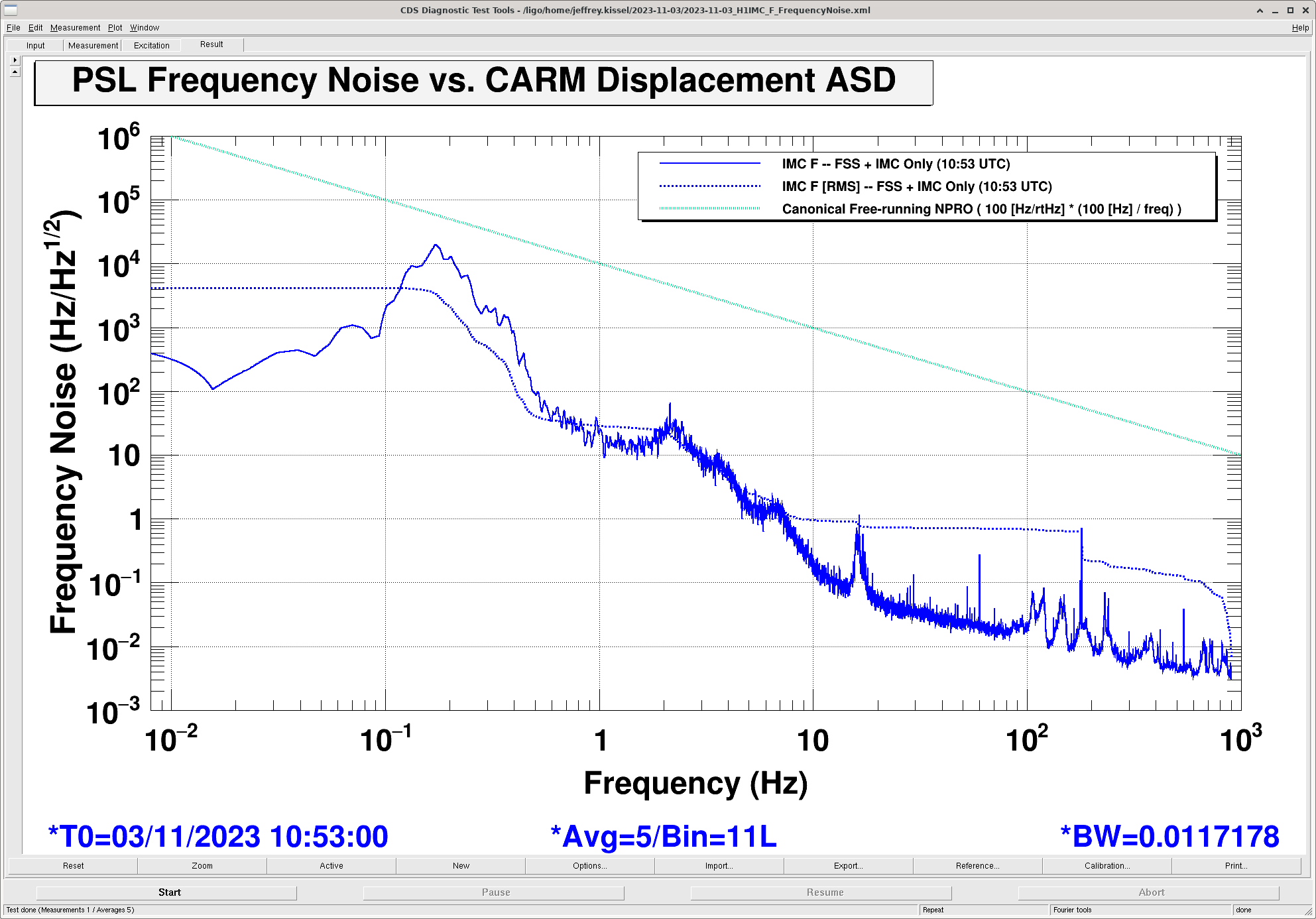
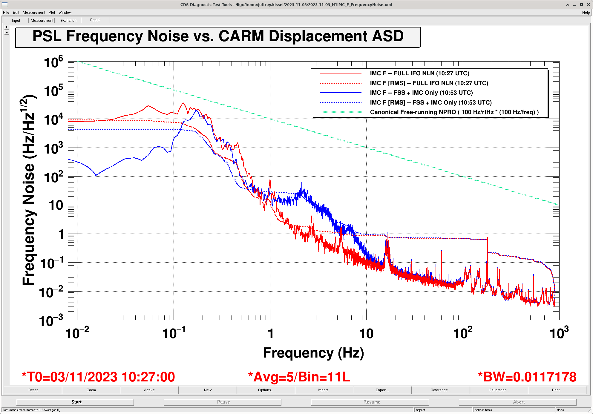
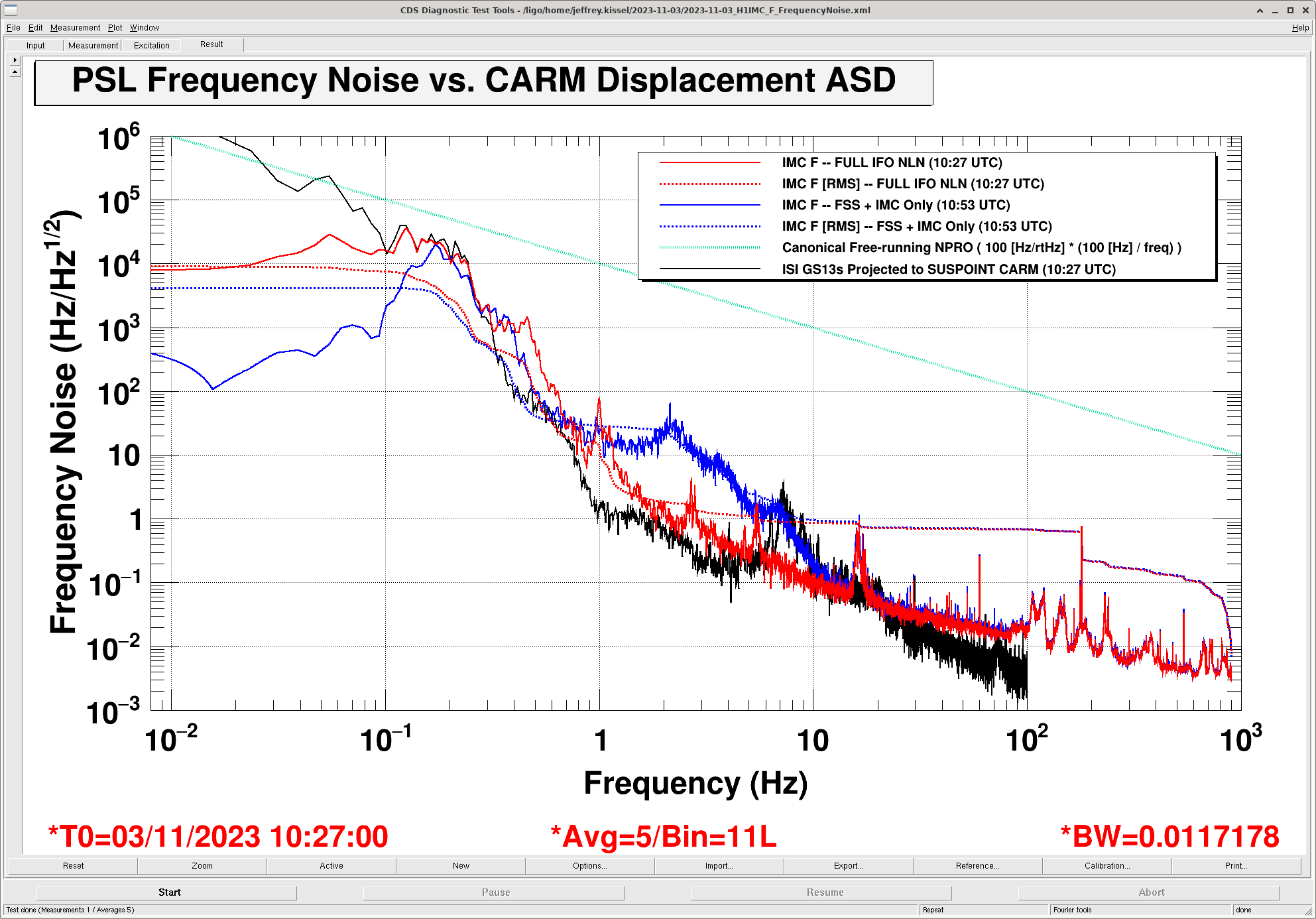
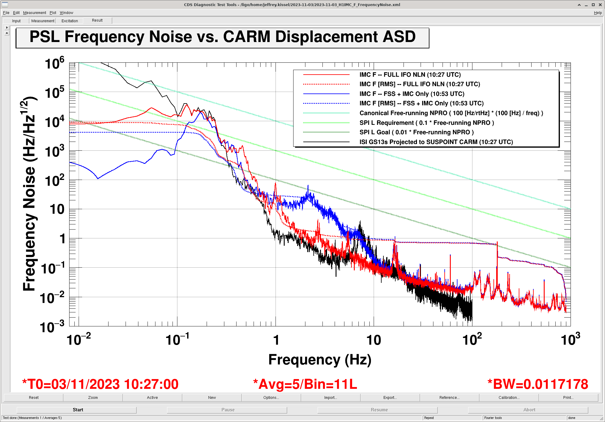
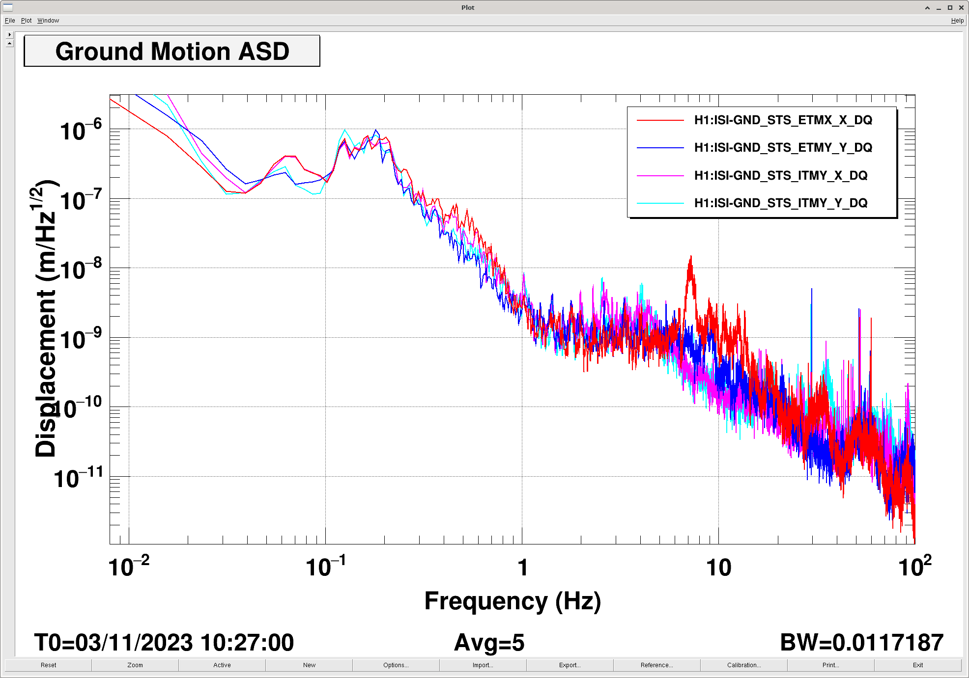
J. Kissel (encouraged by S. Dywer, D. Sigg)

Continuing along with the plan of building up a complete picture of the PSL frequency noise as a part of understanding the future *effective* frequency noise delivered via fiber to a seismic platform IFO for longitudinal control (aka SPI L, started elsewhere using the PMC LHO:73905), today I switch tactics and look at the main IFO's frequency stabilization servo.

Today's primary metric is "IMC_F," i.e. the demodulated output of the PD in reflection of the input of the input mode cleaner, a.k.a the IMC REFL PD, which is a part of the global frequency stabilization servo (FSS) for the detector's pre-stabilized laser (PSL) frequency. For more details on how the global frequency stabilization works, check out the most recent published info on it from Craig Cahillane's paper P2100219 and Chapter 3 section 4 of his thesis P1800022. In short, it's a cascaded set of loops that use
   - the in-vac, rigid-body ~1 m, reference cavity within the PSL,
   - the suspended in-vac ~16 m input mode cleaner, then
   - the common motion of the suspended in-vac 4 km arm cavities themselves
as frequency reference, with ~300 kHz, ~60 kHz, and ~20 kHz UGF, respectively.

This IMC REFL PD's output is converted into a control signal to be pushed to the PSL laser frequency with the IMC "common mode board" analog servo. The output of that analog control filter is digitized and converted into Hz. Because the FSS + IMC + CARM bandwidths are all above 20 kHz and I'm looking at the PD's output below 1 kHz, we're very much in the "infinite gain" region of the control signal. Thus -- assuming we know the frequency actuator calibration (i.e. the voltage-controlled oscillator drive chain) -- then this control signal can be scaled directly to frequency noise without knowledge of the loop. I didn't do anything here, I'm taking advantage of the filtering that's already in place from the original 2013 characterization / calibration -- see LHO:5945 for details. I'm just reading out the channel H1:IMC-F_OUT_DQ, which is actually calibrated into kHz, and multiplying by 1e3 [Hz/kHz].

I look at this metric in two different states of the detector:
    2023-11-03 10:53 UTC -- Reference Cavity and IMC are stability locked vs.
    2023-11-03 10:27 UTC -- just prior, when the IFO is in nominal low noise, i.e. FSS and IMC and CARM are locked

As a reference, since folks are not typically used to looking at the frequency noise of the stabilized PSL below 10 Hz, I also show the cartoon trace of the canonical frequency noise of a "free running" NPRO, 100 Hz/rtHz at 100 Hz, and falling proportionally with frequency, i.e.
    df = 100 [Hz/rtHz] * ( 100 [Hz] / freq )

This puts the "free running" PSL NPRO frequency noise, if it weren't stabilized at all, at 1e5 [Hz/rtHz] at 0.1 Hz -- i.e. the microseism.

OK, so, to the attachments. I attach four cascading plots of frequency noise where I'm adding more and more traces to the same plot as the plot number increases. Open them all up in tabs, and then walk through them slowly as follows:
(I) 2023-11-03_H1IMC_F_FrequencyNoise_01.png -- this shows IMC F stabilized with just the RevCav+IMC used as reference in blue. This is our starting point for building up an understanding, and I keep the NPRO free-running frequency noise in dashed sea-green. In this attachment you can already kind of guess what's happening.
    (1) Above 10 Hz, there's some noise that falls as (1/f). Littered throughout that noise, are some acoustic peaks scattered throughout. BUT
    (2) Below 10 Hz -- and particularly around 0.1 Hz we see a quite familiar shape -- that of ground motion around the microseism.

(II) 2023-11-03_H1IMC_F_FrequencyNoise_02.png -- this shows IMC F in nominal low noise, stabilized against with RevCav, IMC, and CARM used as reference. The changes actually help further ellucidate and validate the story:
    (3) Above 10 Hz, the (1/f) noise doesn't change. Fine.
    (4) Below 10 Hz, the part of the spectrum we thought was seismic is indeed changed dramatically:
        (a) The 0.5 to 10 Hz region looks to convert
             (i) from a noisy-ish displacement noise -- that looks a lot like the shape of 0.5 to 10 Hz noise budgets from HAM2-HAM3 optic motion -- dominated by the HSTS MC1, MC2, and MC3 OSEM sensor noise re-injected through the damping loops
             (ii) to better displacement noise of optics quadruply suspended from a collection of BSC-ISIs
            retaining the the shape of first two quad longitudinal resonances at 0.43 Hz and 1.0 Hz, and then falling into the ever present (1/f) noise -- now "earlier" / lower in frequency at around 2 Hz.
        (b) Below the 0.15 Hz microseism peak, we see kinda also what we expect -- that the BSC-ISIs are re-injecting a lot of local tilt into the local longitudinal motion of each of the test masses, and is creating common longitudinal noise in CARM -- increasing the spectral density by a factor 50x, but the RMS only by a factor of 2x because the 0.15 Hz microseism peak dominates the RMS.

To further re-enforce that this is real seismic motion -- I recall that we've done a lot of work converting all ISI's GS13s -- include those of the BSC-ISIs suspended the QUADs -- into local suspension point motion -- and then even further converting those local suspension point motions into the basis of the IFO cavities.
    H1:OAF-SUSPOINT_CARM_OUT_DQ
is that ISI GS13s for the QUADs converted into local Sus. Point and then to CARM all coherently. So, if we convert this to frequency noise, via
    >> c = 2.9989e8;
    >> L = 3995;
    >> lambda = 1064e-9;
    >> (c / (lambda*L))
        ans =
            7.0551e+10 [Hz/m]

and because the all GS13s are calibrated into nano-meters, we get the final "frequency noise" calibration of these channels as
    >> 1e-9 * (c / (lambda*L))
        ans =
            70.551 [Hz/nm]

then we land on the black trace in
(III) 2023-11-03_H1IMC_F_FrequencyNoise_03.png
    I'm not gunna lie, I'm *delighted* at how well this matches up with what I expect!
    (a) in the 0.5 to 10 Hz region, comparing black to red, we confirm that the QUAD modes are amplifying the ST2 motion on resonance at 0.43 Hz and 1 Hz --and maybe 2.7 and 5 Hz.
    (b) but look at how identically matched the motion is from 0.1 to 0.2 Hz! WOW Wow wow.
    (c) We can tell though, that the GS13s themselves are not reporting real motion below 0.1 Hz -- they're are either "tilt dominated" or "self noise" dominated or something.

But, for me, this confirms without-a-doubt the thing that Daniel and Sheila "knew all along" that "at the microseism, the laser PSL frequency is just following the ARMs."
Maybe someone has plotted this up before for, but I couldn't find it. Anyways, very convincing, and very enlightening.

Finally,
(IV) 2023-11-03_H1IMC_F_FrequencyNoise_04.png compares this BLUE and RED answer against our bigger picture question -- how does this relate to what we need for SPI L? It looks like it may meet our "bare minimum" needs, but will become interesting if we're trying to push the performance of the SPI.
     Very interesting indeed....

Anyways, just for another point of reference, I also show the ground motion at all stations in X and Y -- since this is another thing that folks are used to looking at (rather than the SUSPOINT CARM). This gives you the feel that this measurement is during a "medium" microseism day, with little-to-no wind.
Images attached to this report
Comments related to this report
Attached are the data from this aLOG, exported from the DTT template:
    RED: IMC_F when Full IFO was locked, 10:27 UTC freqnoise_IMCF_FullIFO_kHz_per_rtHz_ASD.txt
    Blue Trace: IMC_F when only IMC and FSS were locked, 10:53 UTC freqnoise_IMCF_IMCFSSOnly_kHz_per_rtHz_ASD.txt
    Black Trace: OAF CARM when Full IFO was locked, 10:27 UTC freqnoise_OAFCARM_FullIFO_m_per_rtHz_ASD_use70p551Hzperm.txt

Note these data are *not* calibrated, or rather, they carry with them the calibration that came with the channel rather than the addition steps it took to get them in the same Hz/rtHz units. Once you load in the data,
- Multiply the IMCF ASDs by 1000 [Hz/kHz]
- Multiple the OAF CARM by 70.551 [Hz/m]

To recreate the DTT plot with matlab and these attached text files:
>> imcf.fullifo.kHz_per_rtHz = load('freqnoise_IMCF_FullIFO_kHz_per_rtHz_ASD.txt');
>> imcf.imcfssonly.kHz_per_rtHz = load('freqnoise_IMCF_IMCFSSOnly_kHz_per_rtHz_ASD.txt');
>> oafcarm.fullifo.m_per_rtHz = load('freqnoise_OAFCARM_FullIFO_m_per_rtHz_ASD_use70p551Hzperm.txt');
>> loglog(imcf.fullifo.kHz_per_rtHz(:,1),imcf.fullifo.kHz_per_rtHz(:,2)*1000,...
          imcf.imcfssonly.kHz_per_rtHz(:,1),imcf.imcfssonly.kHz_per_rtHz(:,2)*1000,...
          oafcarm.fullifo.m_per_rtHz(:,1),oafcarm.fullifo.m_per_rtHz(:,2)*70.551);
>> legend('IMC F, Full IFO 2023-11-03 10:27 UTC',...
          'IMC F, IMC+FSS Only 2023-11-03 10:53 UTC',...
          'OAF CARM, Full IFO 2023-11-03 10:27 UTC')
>> xlabel('Frequency (Hz)')
>> ylabel('Frequency Noise (Hz/rtHz)')

(and you can add the free running NPRO noise model, SPI requirement, and SPI goal traces to the plot by loading in the files as they are, since I generated them by hand and did so in [Hz/rtHz]. These are also attached for your convenience.)

The DTT template and this data are also committed to the SeiSVN here:
    /ligo/svncommon/SeiSVN/seismic/Common/SPI/Results/
Non-image files attached to this comment
