stefan.ballmer@LIGO.ORG - posted 21:23, Tuesday 13 August 2013 - last comment - 19:49, Wednesday 14 August 2013(7434)
Draft for green arm initial alignment system
Out of the 4 DoF (arm optical axis pos and angle, green input beam pos and angle, 2x for pitch and yaw not counted), 3 DoF will likely need a frequent initial alignment - the input beam position at the ETM is the one DoF that remains fixed.
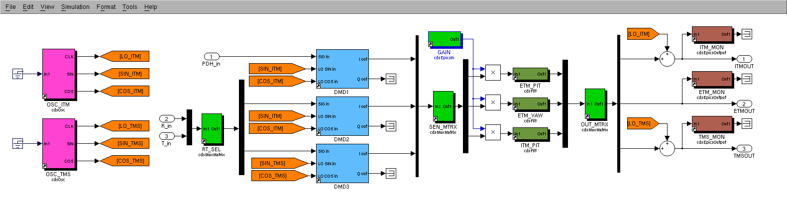
Below is a short description of the suggested alignment loops. Attached is a draft RTCDS model block for e.g. X-arm pitch (we need 4 of them for X/Y P/Y).
Signals to be demodulated:
L: cavity PDH length error signal (green)
R: cavity reflected power (green)
T: cavity transmitted power (green)
Actuation basis (in rad):
(ITM, ETM, TMS)
g-factors:
g1=1-L/R1;
R1= RoC of ITM
g2=1-L/R2;
R2= RoC of ETM
Dither drive frequencies:
f1: ITM dither frequency
fT: TMS dither frequency
Control loops:
1) Fix ITM actuation node
L --->x ---> CTRL_FILT -----> (g1,1,1)
^
|
f1
Remark:
- Actuation at 1.65-2Hz or above 4Hz seems possible in pitch
- Pitch centering offset at 1.7Hz: ~2.3mm (slightly freq. dependent)
- Pitch centering offset above 4Hz: ~4.7mm
- Could provide a slight additional length drive to compensate this offset
- no such issues for yaw
- Actuation leaves the following quantities unchanged:
- arm axis position on ETM
- angle between arm axis and input beam
2) Input beam to arm axis angle overlap at ETM focal point
R or T ---> x ---> CTRL_FILT -----> (1,g2,g2)
^
|
f1
Remark:
- Actuation leaves the following quantities unchanged:
- arm axis position on ITM
- arm axis to input beam separation at ETM focal point
- input beam position at ETM (trivial)
3) Input beam to arm axis angle overlap at ETM
R or T ----> x ---> CTRL_FILT -----> (0,0,1)
^
|
fT
Remark:
- Actuation leaves the following quantities unchanged:
- arm axis position and angle
- input beam position at ETM (trivial)
Alternatives:
- GigE camera centering on ITM (instead of 1)
- ETM dither possible, but due to the steep drop-off of the Quad actuation, I expect reasonable drive amplitudes (producing a decent dip in power buildup) to only be possible at very low frequencies. As a result, since the dither frequency separation dictates the achievable bandwidth, it might be difficult to run all dither loops at the same time.
General Remarks:
- The dither drive is done in the optics basis, because any other basis would require significant attention to the relative phase of different actuation functions.
- To be able to run the loops in sequence, an orthogonal actuation function is desirable.
- repeat procedure of X- and Y -arm, pitch and yaw
- Once both arms are aligned, turn this feed-back off.
Images attached to this report
Comments related to this report
(Sheila, Stefan)

Looking at the trend data (mostly OSEMS) of PR3 PR2 and PRM, it looks like they can drift by up to about 10urad in both pitch and yaw over the course of several days.

We were curious what that means for initial alignment requirements. So we put together a ray transfer matrix model based on LIGO-T0900043: “Optical Layout and Parameters for the Advanced LIGO Cavities”. With that we looked at how much the beam spot on the ETMs would move given the 10urad drift (the factors of 2 are due to reflection on the mirror):

PR3: 2x 4.0 mm/urad * 10urad ~ 80mm (compare to beam spot size of w=62mm - motion too big)
PR2: 2x 0.44mm/urad * 10urad ~  9mm
PRM:      7 um/urad * 10urad ~  0.07mm (tiny!)

SO:
- PRM will be just fine, and won't need any daily realignment.
- PR2 seems to be borderline - probably good enough for locking, but might need the occasional tweak.
- PR3 (&BS) will definitely need an alignment. The logical place for this would be during the green locking - we might want to add green QPDs on ISCT1.


Similar conclusions will hold for the SRC (once its installed). Here an initial tweak-up of SR3 can be done with the AS_DC QUAD on HAM6.