Summary:
OMC DCPD/QPDs/PZTs are good without caveat for the first time in LHO history.
OM2 heater and thermistors are good.
ASC-AS_C has a grounding issue which should be fixed in chamber at some point.
Didn't check grounding of the beam diverter and picos (confirmed that picos move, didn't test BDV).
For flange layout, see D1002877 (but note that LHO uses D6-F4 for OMCR diode, not D6-F6).
For in-air wiring, see D2200215 (OMC DCPD), D1300589 (OMC PZTs), D1002283 (OMC QPDs, OMCR DCPD also uses one channel of the QPD interface), D2000212 (T-SAMS heater/thermistor).
New OMC seems to have eliminated the source of headaches in the past.
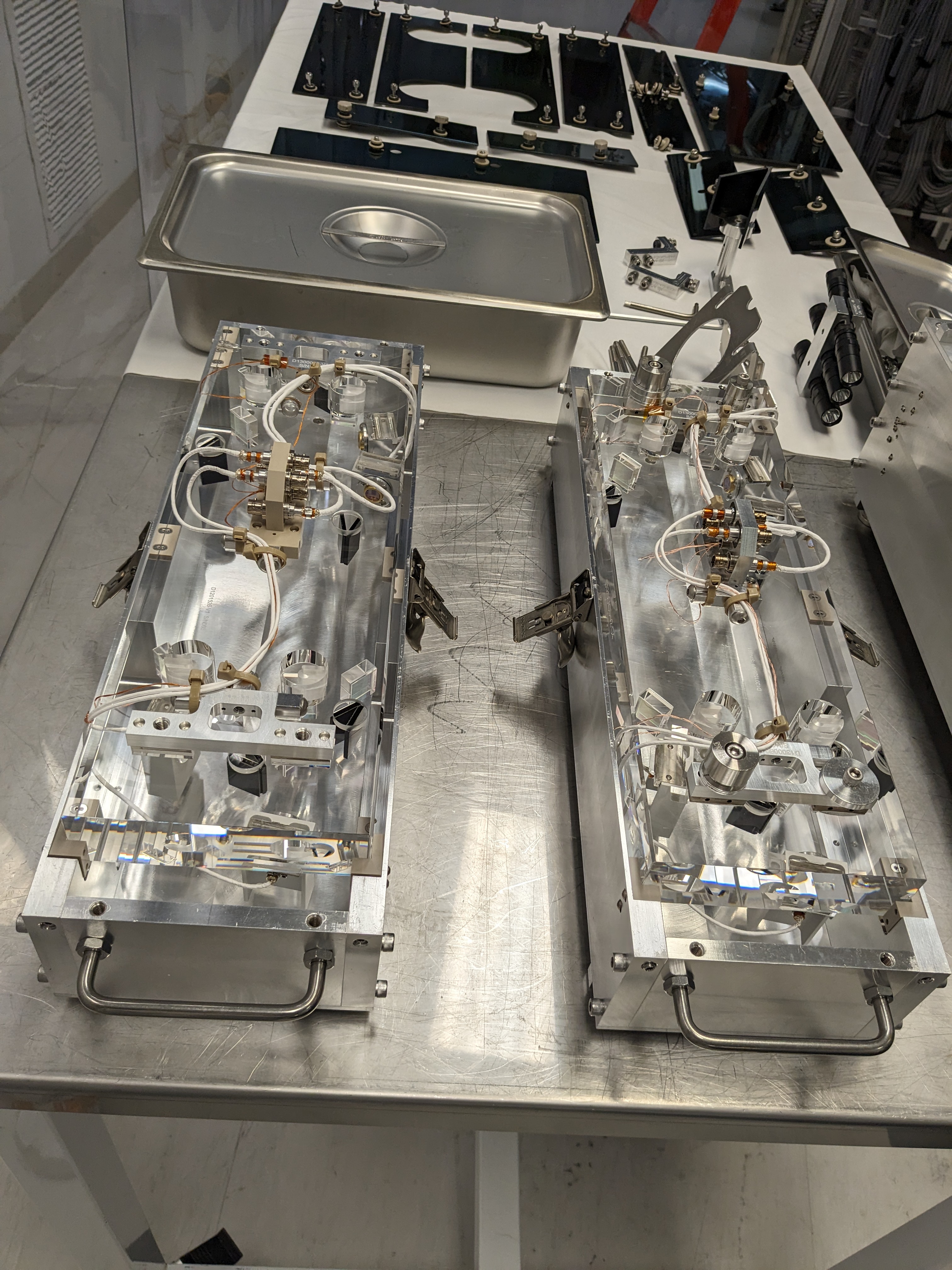
The new OMC (1st attachment left) has a PEEK connector bracket on top of the OMC breadboard instead of an aluminum bracket (1st attachment right). In the past this aluminum bracket caused many, many headaches. Now that it's gone, OMC DCPD/QPD/PZT chain makes sense w/o caveat.
D6-F1 (DCPD/Preamp)
At the feedthgough, I disconnected the D6-F1 DB25 (for OMC DCPD/Preamp) and used a breakoutboard on the feedthrough to check grounding. No pin including pin13 (that is used for shield) is connected to the chamber. Pin 13 is only connected to signal GND pins of the in-vac preamp (pin 10/15/16/19/20/23).
Inside the chamber on the in-vac preamp, the DB25 shell is connected to the preamp body (which is isolated from the ISI via PEEK spacer). At first DB25 shell and the preamp body was shorted to the ISI table, but this turns out to be via 3MHz cable ultimately connected to the in-air chassis. As soon as both of the 3MHz cables were discunnected from the in-air chassis, preamp body as well as the DB25 shell weren't conducting to the ISI table any more.
D6-F1 and 3MHz connection.
D6-F2 (PZT)
Disconnected D6-F2 (PZTs) at the feedthrough, used a breakout board. Discharged the PZTs. Measured capacitance: HZ PZT (pin1-14) was 373nF, LV PZT (pin2-15) 392nF, these include in-chamber cables. Nominally these are 380nF and the measured numbers are good.
Pin 13 is not connected to any pins nor the chamber. No short circuiting between LV and HV path.
Restored D6-F2 connection.
D6-F3 (QPDs)
Disconnected D6-F3 (OMC QPDs) at the feedthrough, used a breakout board.
Pin 13 is not connected to any pins nor chamber. Diode connection from QPD1 anode 1/2/3/4 (pin 15/2/14/1) to QPD1 cathode (pin 16). Diode connection from QPD2 anode 1/2/3/4 (pin 18/5/17/4) to QPD cathode (pin 19). No connection from QPD1 to QPD2 and vice versa.
Restored D6-F3.
OMCR diode is good
Disconnected D6-F4 to check. Pin 13 is not connected to chamber nor any pins. Restored D6-F4.
ASC-AS_C has a grounding issue
Disconnected D6-F5 to check. Pin 13 is connected to the chamber. Restored D6-F5.
T-SAMS heater/thermistors are good
Disconnected D6-F9 to check.
Pin 13 is not connected to chamber nor any pins.
Pin 1-14 (heater) is 104 Ohm, which is good.
Pin 11-24 (thermistor 2) and pin 12-25 were both 11.7kOhm, sounds about right. No cross-connection between thermistor 1 and 2.
Things that weren't checked
Will check grounding:
Pico (checked that both WFSA and B pico moved).
WFS (DC).
Suspensions. Will leave it to Fil.
Won't recheck grounding:
Beam diverter (will check that it moves). Known in-chamber grounding, this was dealt with in air in the past, no reason it changed.
WFS (RF, interface). Coax, no reason to worry.
DCPD 3MHz. Coax, no reason to worry.
Tagging with EPO for OMC mass comparison.
Added later: WFS (DC), Picos, and Fast Shutter are good.
D6-F7 (pico):
See D1100326 for pin connections. Disconnected the DB25 at the feedthrough and used a breakout board.
No pin (incl. pin 13) is connected to the chamber ground. Pin 13 is not connected to any other pins.
WFSA and WFSB DC:
See D1300467 for pin connections. These are on D3-2C1 and 2C2, but they're almost impossible to access, so I disconnected the DB15 from the front panel of the WFS interface, attached DB15 breakout board to the cable and checked. (Note that they use special DB25-DB15 cable to make a connection between the feedthrough and the interface.)
For both of the cables, DB15 connector shell is only connected to pin 14 and 15 (signal ground for in-vac WFS board), not connected to the rack ground.
Fast Shutter:
See D1400225 for pin connections. This is on D3-3 but it's almost impossible to access, so I disabled the HV for the FS driver, disconnected the 6-pin HV connector from the front panel and checked the connection betweein the cable pins.
No pin is connected to the rack ground. No cross connection between positive drive, negative drive and continuity check pins.