This log follows up some previous work that's been done to understand the LSC, in particular MICH, noise coupling that we have observed. The most recent work done on this front was by Dana, in alogs 74477 and 74787. Notably, the MICH coupling follows an interesting shape here, especially below 20 Hz. For MICH, we expect a flat coupling depending only on the finesse, Gm = pi/2*F. Evan Hall made some great measurements of this coupling years ago and you can see the results in Fig 2.17 of his thesis(link to thesis)- without any feedforward the magnitude of the coupling is flat in frequency down to 10 Hz. However, Dana's measurements clearly show a frequency dependent coupling below 20 Hz. Also, Dana mentions that the MICH coupling is about 40% too high than we expect based on finesse.
I'll add here a quick note that currently the UGF of MICH is about 8 Hz and the UGF of SRCL is about 11 Hz, so I think it's safe to assume that we are not seeing any significant closed loop effects from either of these loops down to about 12 Hz in these measurements.
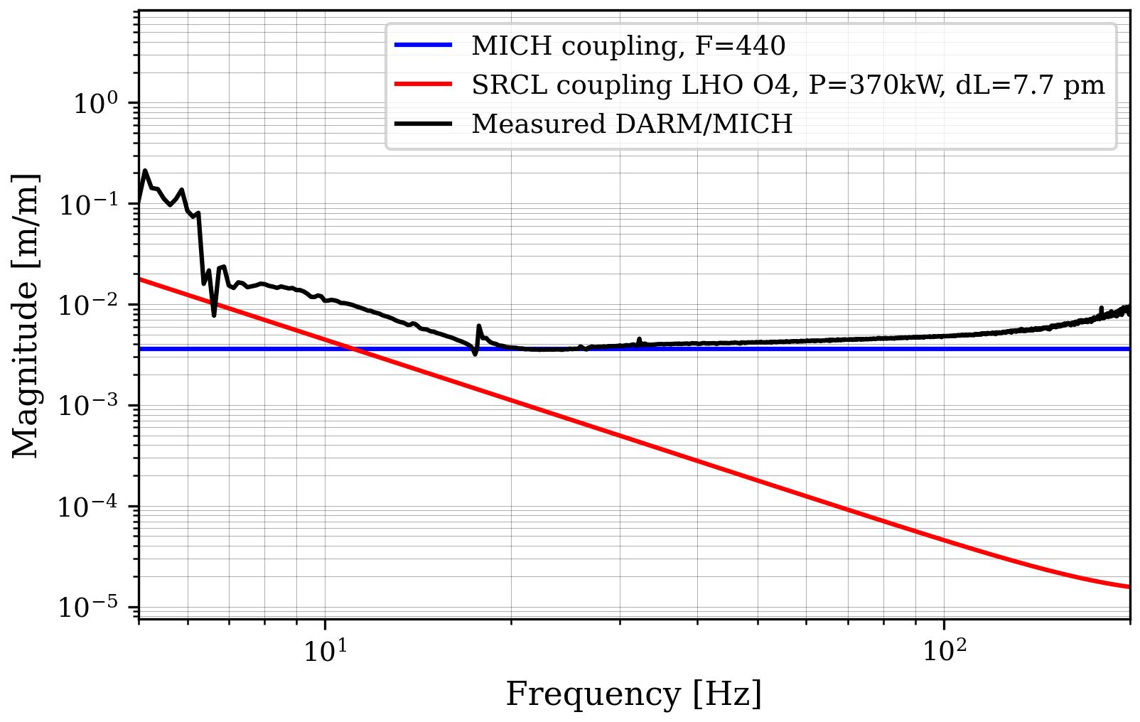
Something to remember here is that when we measure the MICH coupling we drive the beamsplitter which does induce a change in the MICH length, but it also changes the SRCL and PRCL length. Therefore, we should expect to pick up SRCL coupling along with the MICH coupling when we measure. Evan's thesis also includes the form of the SRCL coupling in Eq 2.29: Gs = 0.012 [m/m] * Pa/750 [kW] * dL/10 [pm] * F/450 * (10 [Hz] / f)^2 (I am only including the first term that dominates at low frequency). The SRCL coupling results from radiation pressure in the SRC due to the DARM offset (dL), power in the arms (Pa), and finesse (F) and follows a 1/f^2 slope (again, I am ignoring the second term here that rises like f^2 at high frequency). We are operating at much higher power and double the DARM offset, Pa=370 kW and dL = 20 pm (and F = 440).
Regarding the 40% excess MICH coupling, if you divide Dana's result by an additional sqrt(2), it lines up exactly how you would expect. Is there a chance the MICH calibration is missing a rt2 factor related to the fact that we measure from the beamsplitter?
Assuming I'm correct about the sqrt(2) factor, and plotting the magnitude of the expected MICH and SRCL coupling along with Dana's calibrated measurement, our expected O4 SRCL coupling lines up almost exactly with the response at 20 Hz and below (see first attached plot).
I think this effect has always been there, but not easily observable because the SRCL coupling was much lower due to lower operating power and smaller DARM offset. Comparing Evan's MICH coupling measurement (Fig 2.17) with his SRCL coupling measurement (Fig 2.18), the SRCL coupling at 20 Hz was close to an order of magnitude lower than the MICH coupling.
I think this understanding of the coupling better explains why we need to put so much work into the LSC feedforward. Specifically, we measure the coupling for MICH and SRCL, and then usually tune MICH first and then SRCL. Then, to do our iterative tuning, we redo the MICH coupling. It's likely we could do a better job first just tuning SRCL and then measuring and tuning MICH, since we need to subtract the SRCL coupling well enough to get a "true" measure of the MICH coupling.
Furthermore, the SRCL coupling is dependent on our DARM offset. When we make changes to OM2, for example, we change the mode matching at the output. Since we servo to keep the amount of light on the DCPDs constant, we could be changing the required length to achieve this amount of light slightly. In principle, this should only effect the SRCL coupling, but since SRCL shows up in our MICH coupling measurement, it effects both.
Finally, it appears in Dana's measurement that there is a rising trend above 30 Hz, which I have no explanation for. I don't think that can be explained by the SRCL coupling. A look at that second term in the SRCL coupling equation: Gs = 3e-5 [m/m] * phi_s/10 [deg] * dL/10 [pm] * F/450 * (f / 100 [Hz])^2 (Evan's thesis Eq 2.29), I estimate that with a SRCL detuning of about 1 deg, around 30 Hz the SRCL coupling term with an f^2 slope is about 5.3e-7 m/m. This is both too small and the wrong slope to explain that feature.
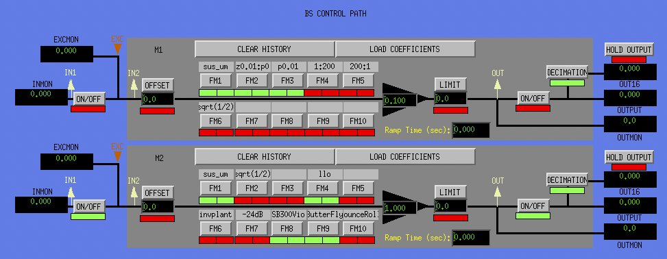
I started poking around the CAL CS screens, and I noticed that the BS control path calibration screen has a "sqrt(1/2)" filter in M1 and M2 that is not engaged. Maybe that solves the rt2 mystery (screenshot attached).
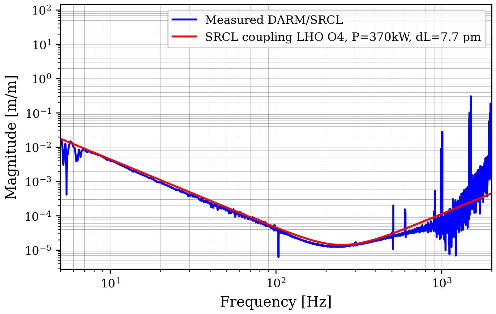
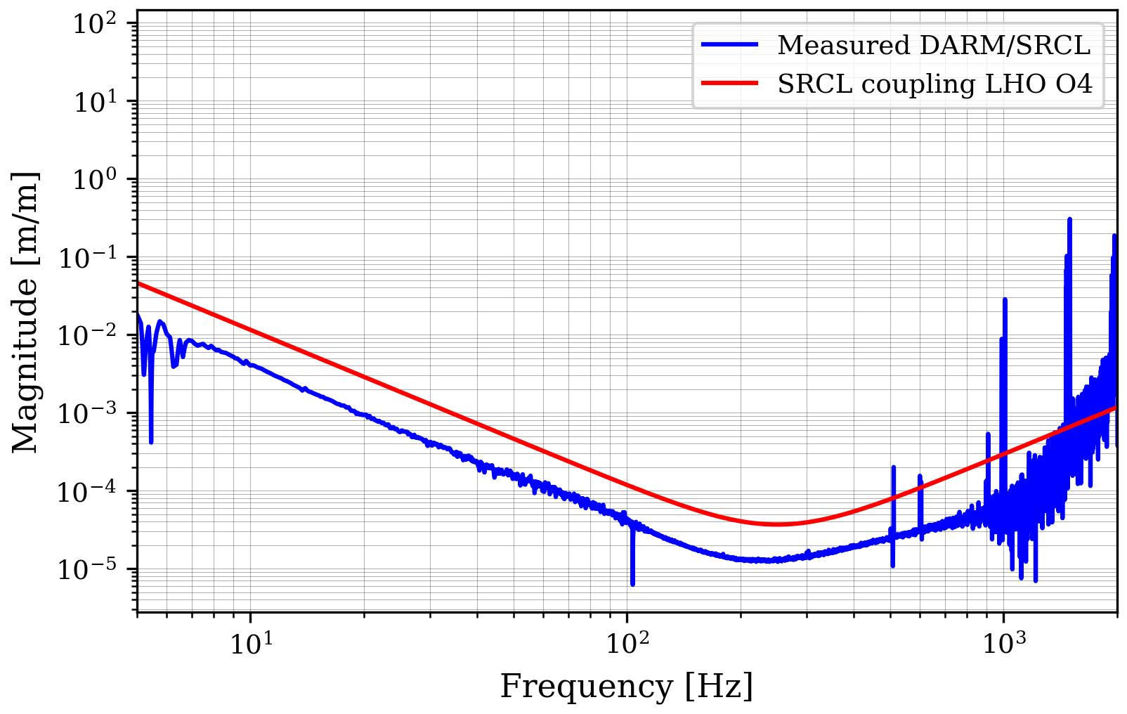
Next, I took a look at the calibrated SRCL coupling. Thanks to Dana's fantastic documentation of the steps in 74477 I was able to generate the calibrated measurement of the DARM/SRCL transfer function (for the time of the SRCL excitation with no feedforward, use GPS time 1371490640). The DTT file is saved as "/ligo/home/elenna.capote/LSCFF/SRCL_DARM_cal.xml"
I exported the data and plotted it against my calculation of the SRCL coupling equation using both terms, Evan's thesis eq 2.29. For the high frequency term that is dependent on microscopic SRCL detuning, I used 0.5 deg (and darm offset 20 pm and finesse 440), which I got to by guessing and matching the trace. See the result in the second attachment.
Overall, the measurement magnitude is too low by a factor of 3. However, the slope matches up quite well. Given that we were apparently missing a rt2 in the MICH calibration, I am convinced that somewhere in the SRCL Cal screen, some filter magnitude is off by 3. Off the top of my head, I know that Gabriele updated the M1 offload filter for PRM and SRM, and that doesn't look like it has been updated in CAL CS. I'm not sure if other aspects are out of date as well. For those comparing the plots, the red SRCL trace in both LSC coupling plots is exactly the same.
Reading Matt's alog calculating the DARM offset (alog 76236), I realized made a pretty big error in these noise coupling calculations. I incorrectly assumed "double darm offset" meant 20 pm instead of 10 pm, but it actually means 40 mW instead of 20 mW. Therefore, I need to calculate what the DARM offset was around the time of these measurements. Dan took some contrast defect measurements at 60W using the O4a TCS settings before we powered up in April (see pdf attachment). I also trended back in time to confirm that this measurement was indeed taken in the 60W configuration.
Dan's measurement shows about 1 mW of contrast defect and b=0.648 mW/pm^2. Therefore, the DARM offset during O4a was likely around 7.7 pm, using 40 mW of DARM offset light (dL = sqrt((40-1)/0.648)). Recalculating the expected SRCL noise coupling value in m/m shows it lines up very well with the calibrated SRCL measurement (see plot). Therefore, my assumption in my previous comment that the difference in expected versus measured value was due to miscalibration seems less likely.
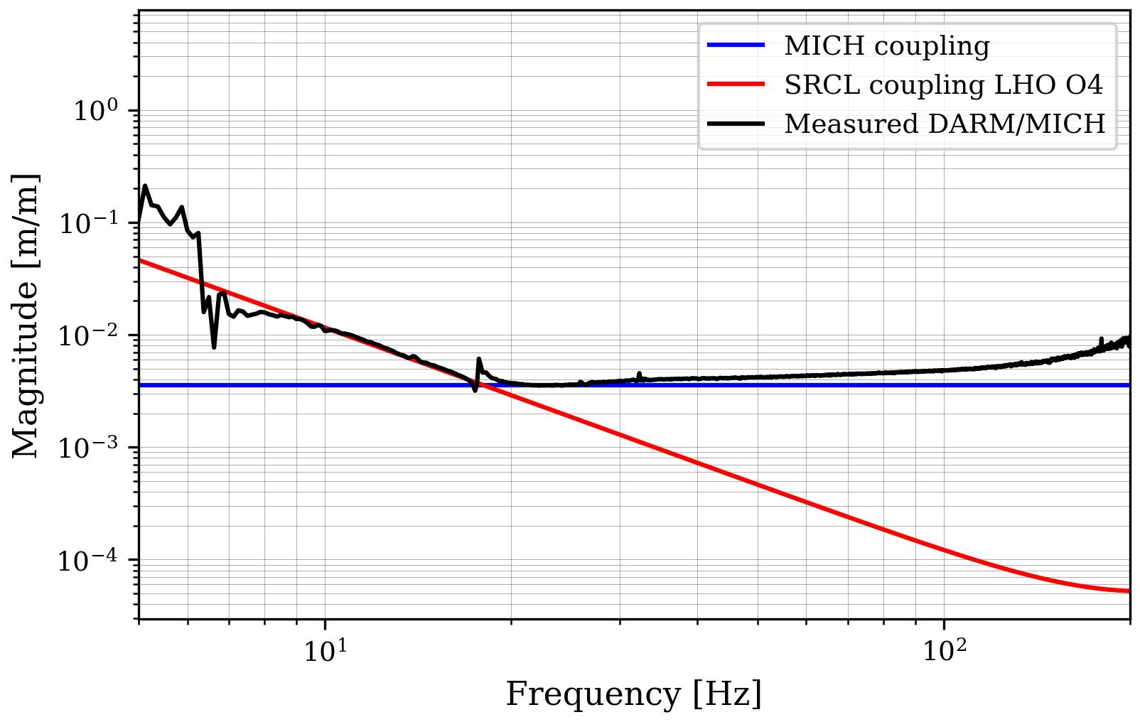
However, this corrected result now casts doubt on my assertion that the MICH coupling behavior at low frequency can be explained by SRCL coupling. Using the corrected DARM offset value shows that the SRCL coupling is less than the observed coupling at low frequency by about a factor of 3 (see plot).