Keita, Jennie W
Keita and I were tuning the alignment of SR2, OM1, and OM3 to improve alignment into OMC after the vent and swap to the new OMC.
We started just after 22:00:00 UTC on the 27th.
Note: HEPI is still locked on HAM5 and HAM6 for vacuum work so we may have to move the mirrors again once these are unlocked.
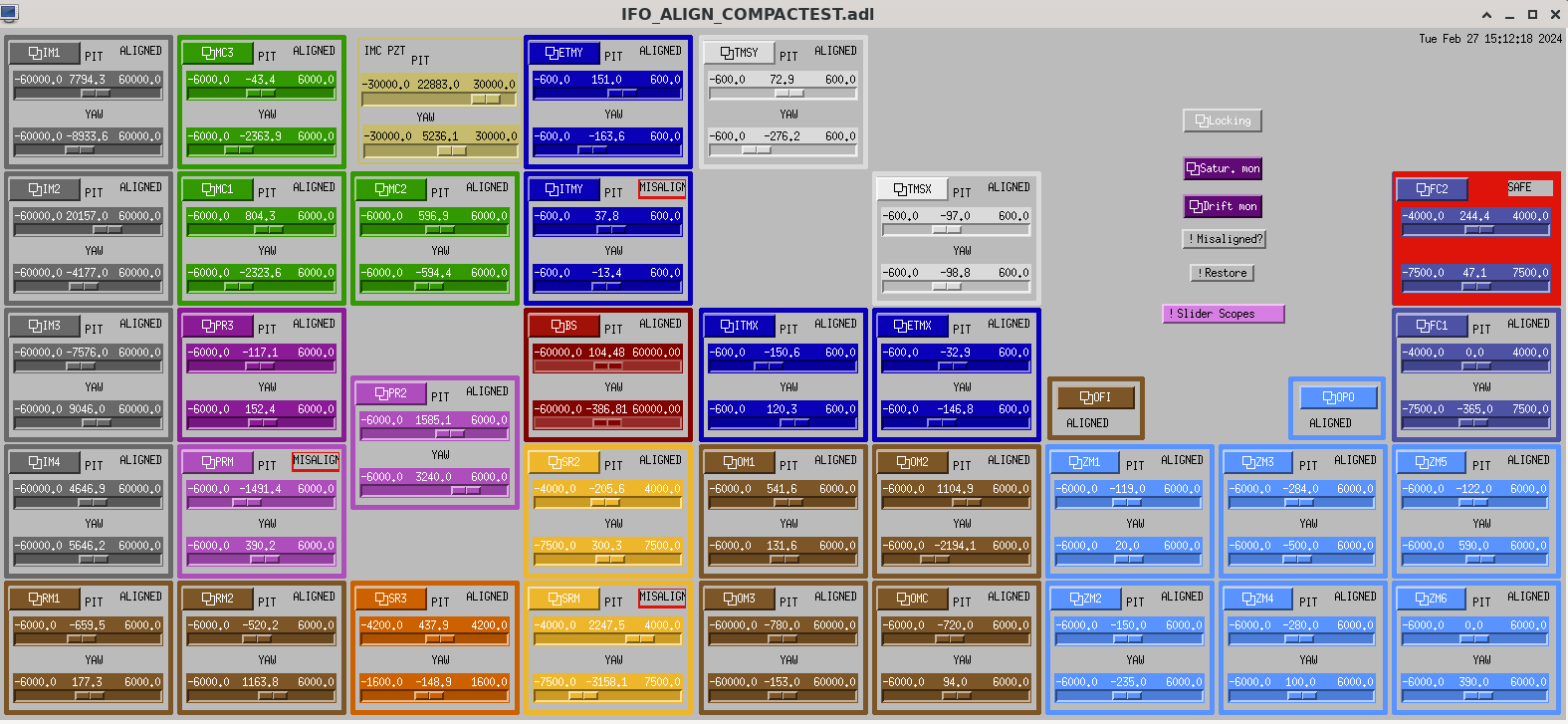
The beam was not well aligned on the AS_C QPD.
Firstly we turned off the the offsets in H1:ASC_OMC_{A,B}_{PIT,YAW,RIN} and in H1:OMC-ASC_QPD_{A,B}_{PIT, YAW} as these are on the output of the OMC QPDs and were set for the old OMC and alignment.
Secondly:
- we turned on the matrix element (INMATRIX_P_7_27) in the ASC PITCH input matrix to route AS_C_DC input to SRC2_P.
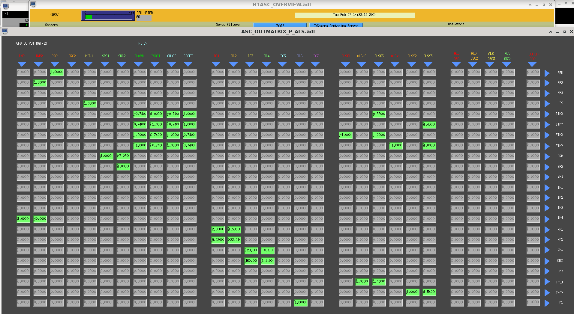
- Then we changed the output pitch matrix element (OUTMATRIX_P_9_7) from -7.08 to 0 to ensure output from SRC2 does not got to SRM.
- We then turned on the gain in the H1:ASC_SRC2P to be 10 so we could align SR2 then get the loop to take over.
- We tweaked up the pitch alignment sliders for the optic to drive ASC-AS_C_SUM to zero until the ASC loop took over.
- We did the same for the yaw degree of freedom.
Thirdly:
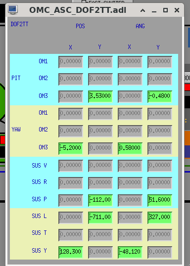
- we changed the OMC_ASC_DOF2TT matric to only feed OM1 yaw to the POS X direction and OM1 pitch to the POS Y direction.
- We ran an excitation on the alignment of OM1 in pitch and yaw till we saw it on ASC-OMC_A phtodiode.
- Then we tweaked the alignment sliders till the beam was well centred in pitch and yaw.
After this we tried turning on the OMC ASC but noticed it ran away in pitch and yaw.
We went into the OM1 sus screen and noticed that there are integrators on in the OM1 M1 Locking Filters, so we should not use additional integrators in the OMC ASC filters in this case. We cleared the hostory and changed the alignment offsets to compensate and get the beam back on QPD A.
Fourthly:
- we changed the OMC_ASC_DOF2TT matric to only feed OM3 yaw to the ANG X direction and OM3 pitch to the ANG Y direction.
- We ran an excitation on the alignment of OM1 in pitch and yaw till we saw it on ASC-OMC_B photodiode.
- Then we tweaked the alignment sliders till the beam was well centred in pitch and yaw.
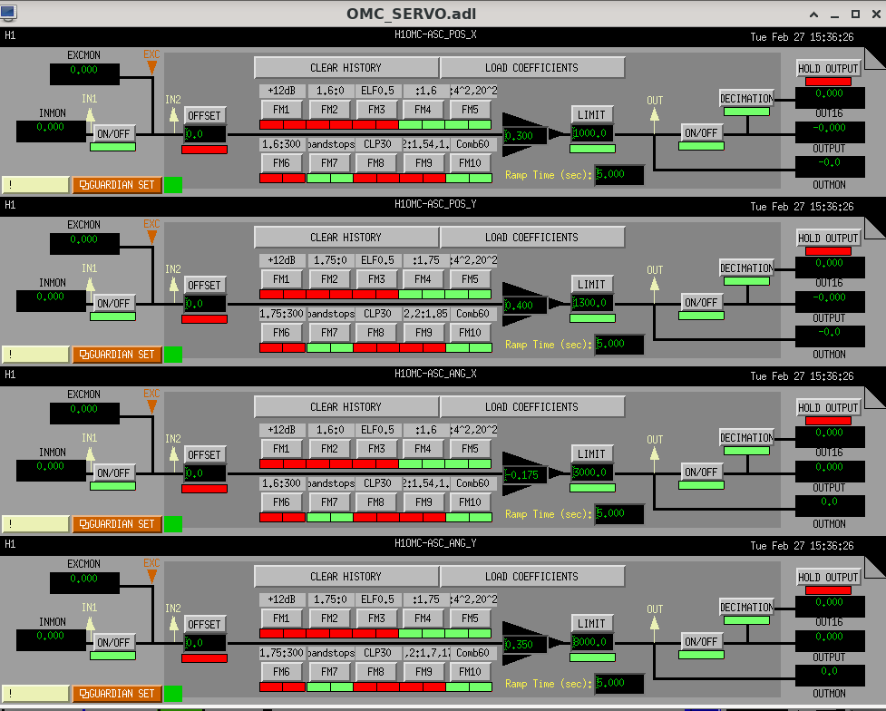
We set each loop up individually with gains that worked but then had to redo these once all four ASC loops were running as there is some cross-coupling.
The two ANG X and Y loops have integrators on as the OM3 suspension does not have integrators in the OM1 M1 locking filters.
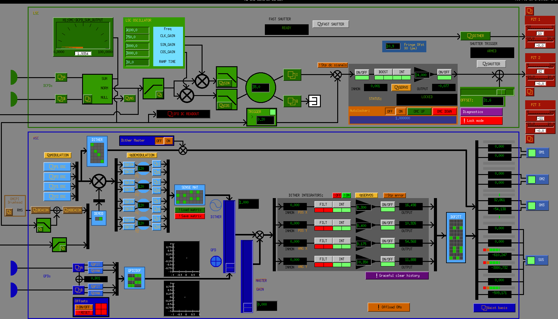
The final loops gains are shown in the first screenshot.
Camilla pointed out that OM2 had high alignment offsets so we tried to slowly tune the pitch offset down while offloading this on the OM3 pitch offset.
Finished our alignment efforts at about 2:00:00 UTC on the 28th.
I have left the overall OMC ASC gains at zero and the SR2_P and SR2_Y gains at zero.
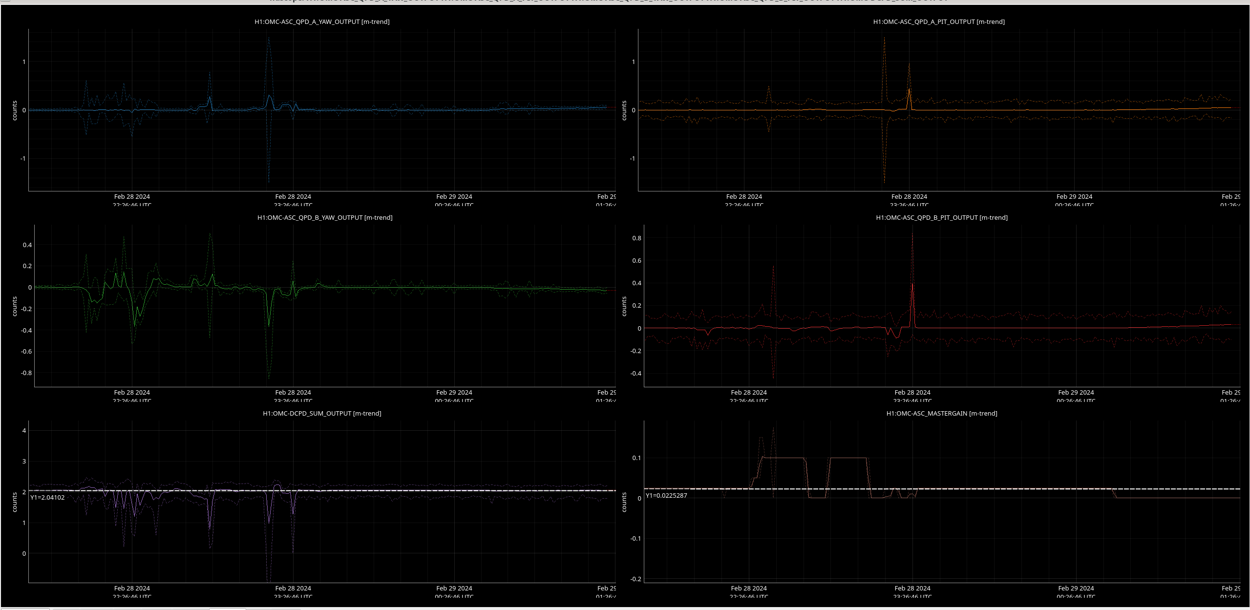
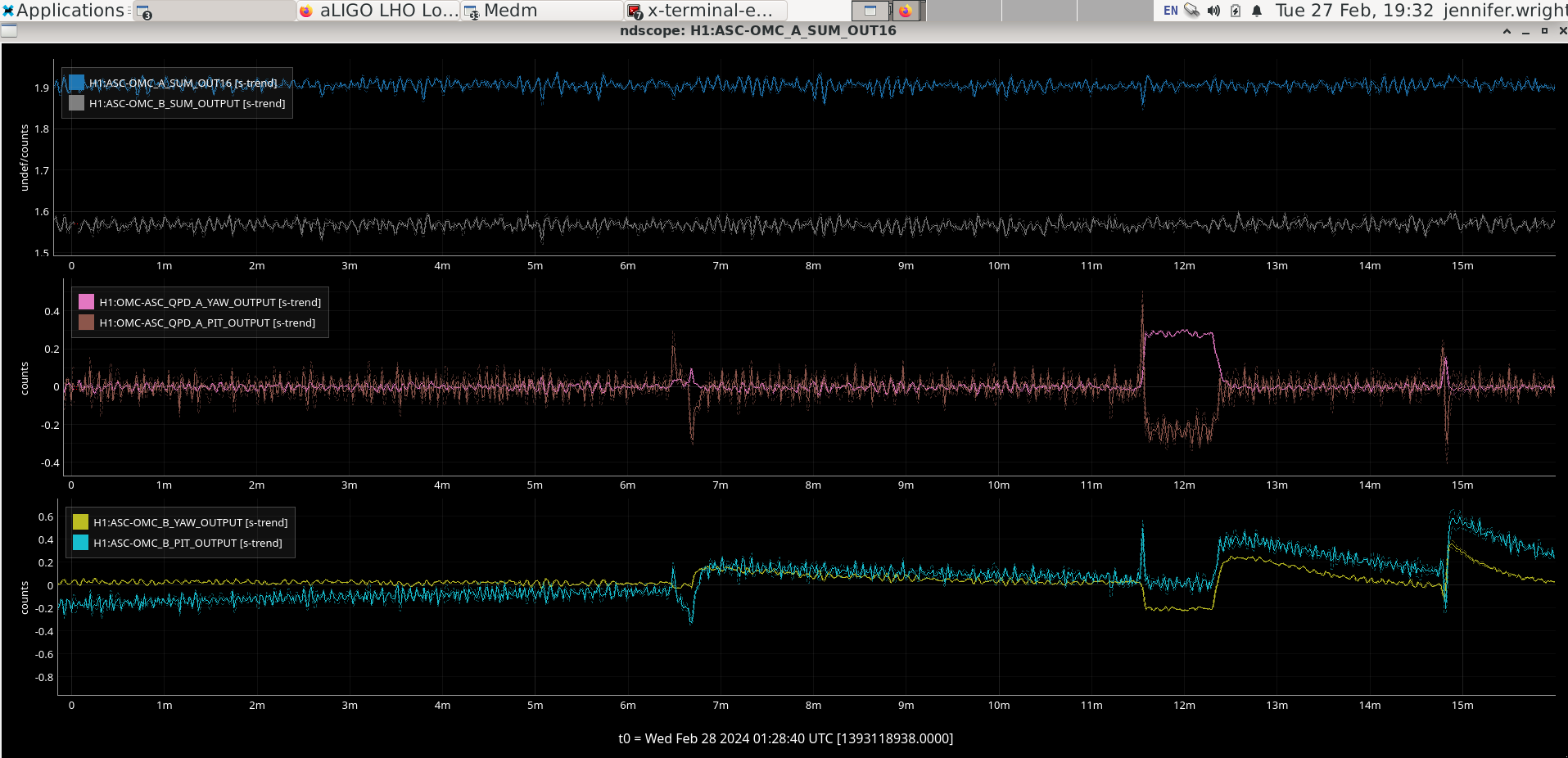
Second image is the OMC QPD SUM outputs and the YAW and PITCH outputs during the last part of the alignment.
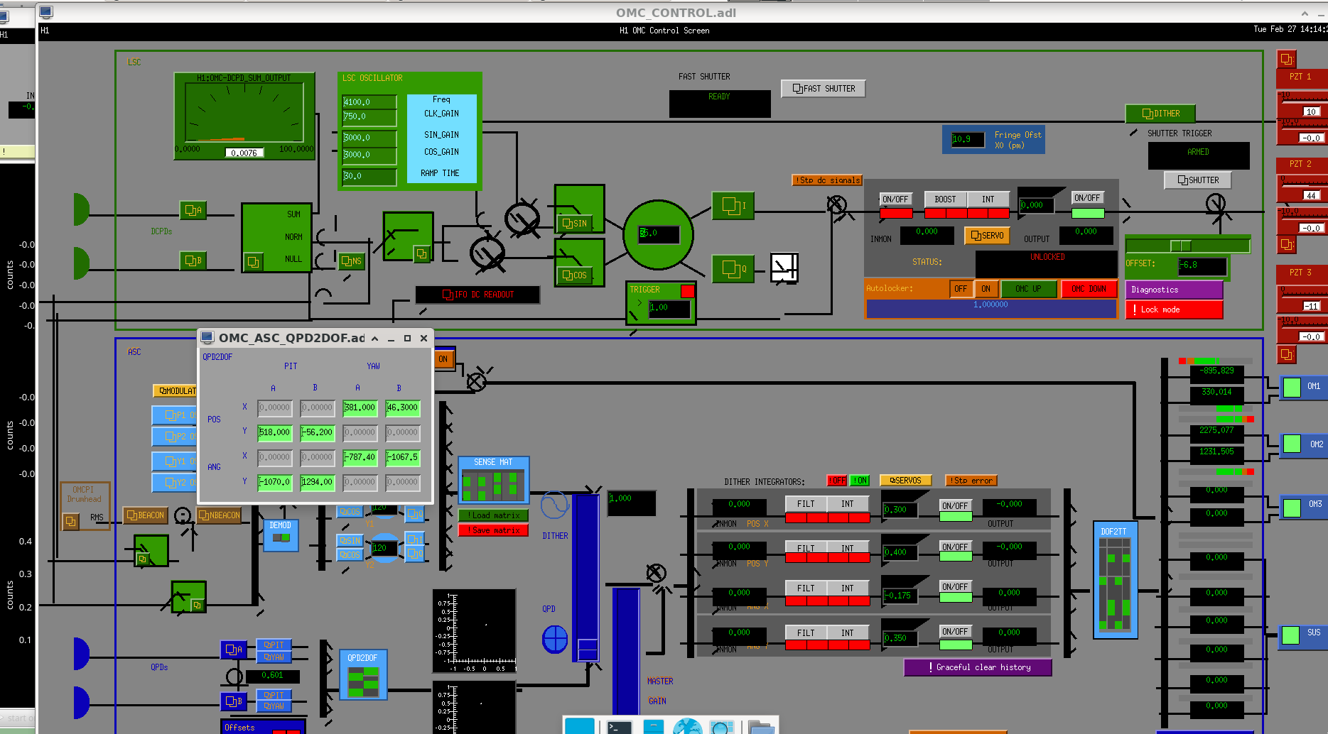
Third screenshot is the OMC control screen before we started.
Fourth screenshot is the ASC P OUTMATRIX before we started.
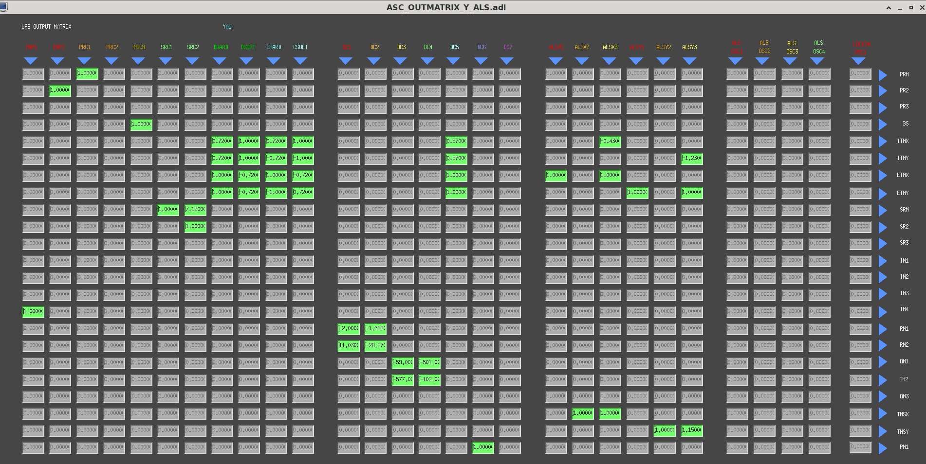
Fifth screenshot is the ASC Y OUTMATRIX before we started.
Sixth screenshot is the slignment sliders before we started (except for some small changes I made to OM1 before Keita came to help). I think the original values for OM1 from yesterday were 651.6 counts in Pitch and 63.6 in yaw.
Seventh screenshot is the OMC_ASC_DOF2TT moatrix before we started.
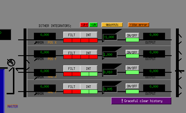
Eighth is the OMC ASC servo filter banks before we started.
Jenne, Jennie W
Before doing any alignment today Jenne ran the dark offset script. See alog.
Keita suggested we offload the alignment into the OMC from yesterday and go back to the ASC loop settings that were 'nominal' before the vent, and also that we may need to use the pico-mirrors to move the beam back onto the WFS behind OM3 (ASC-AS_A and ASC-AS_B).
We were hesitant to use the pico-motors as the arms have not been locked since the vent so some alignment before the OMC will change once the whole IFO comes back up.
Jenne turned on the OMC ASC loops we designed yesterday and offloaded the the alignment of OM3 and OM1 and waited for the loops to converge to ensure when we revert these loops the mirrors will stay aligned. Some tweaking of gains was neccessary.
Then we turned off the loops and reverted the OMC SDFs except for the QPD YAW and PITCH offsets, and the offsets to DCPD A and B.
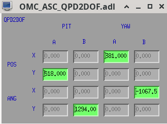
In doing this I noticed that yesterday we had changed the QPD2DOF matrix as well as the DOF2TT matrix which I forgot to note in my log. A picture of it while Keita and I were doing alignment yesterday is the first attached image.
After much waiting and changing the signs of POS X and ANG Y the OMC ASC loops do converge and maintain the alignment onto QPD A and B.
Jenne also moved SR2 to bring the beam back onto AS_C as this had drifted since yesterday.
The ASC loops now work and drive the alignment to 0 on QPD A and B.
Image 2 shows the QPDs and the OMC DCPD sum when the OMC ASC is on - ie. MASTERGAIN is non-zero.
The locked level on the DCPD is 2.04 mA.
I unlocked the ASC loops at 0:41:43 UTC 2024-02-29 UTC as an earthquake was coming through.
Third image is the OMC locking screen showing lock settings for the ASC loops and the length locking for the OMC cavity (except the mastergain is turned off in this image because ASC loops are now off). I will also leave the OMC length servo gain at 0 overnight.