J. Oberling, R. Crouch
Update on FARO work during the O4 commissioning break. Previous updates at the following alogs (with associated comments): 75669, 75771.
Since the last progress update we've been testing our FARO X/Y alignment routines and attempting to re-establish Z=0 based on the door flange scribes on BSC2. We've been navigating Laser Safe/Hazard transitions, as we can only do optical surveying (like using an autolevel for our BSC2 survey) during Laser Safe; the FARO is usable during Laser Hazard so we've been using these windows for FARO work.
FARO X/Y Alignment Testing
As a means of testing the repeatability of the FARO's X/Y alignments we have been using the brass monuments for mechanical test stand #2 (TS2) in the West Bay of the LVEA. The FARO gives us a global X/Y coordinate for these monuments based on our alignment (which is also a local X/Y coordinate since XG=XL and YG=YL), which we can use to compare the Measured Local LVEA coordinates to each other and test the repeatability of different FARO alignments. In addition, each test stand has a monument that represents the [0,0] of the test stand (monument TS2-10 for TS2). We can therefore subtract the local LVEA X/Y coordinate for the [0,0] monument from each measured test stand monument to translate from Local LVEA coordinates to Local Test Stand coordinates. With this translation we can also compare the monument coordinates measured by the FARO to where we think they are via their as-designed coordinates (designed test stand monument coordinates taken from D1100291).
The results are shown in the attached .pdf file 'FARO_XY_Alignment_Test_TS2_Monuments.pdf'; I have also attached the reports generated from PolyWorks for each of our surveys. To date we have done this with 3 separate alignments:
- Alignment 1: BTVE-1 as a sphere, PSI-1, PSI-2, and PSI-6 as points
- Alignment originally created on 2/5/2024 to test differences in using sphere features vs point features; the 3" sphere fit rod was used for BTVE-1 (alog 75771, under Wednesday, 2/7/2024)
- Alignment 2: All alignment monuments as spheres
- Alignment originally created on 1/22/2024 with a 3" sphere fit rod, to compare to the 5" rod and test the accuracy of moving the FARO (done in alog 75669)
- Alignment 3: All alignment monuments as spheres
- Alignment originally created on 2/21/2024 as a new alignment for this test; the 3" sphere fit rod was used
Alignments 1 and 2 give us insight into how using different feature types (points vs spheres) for our alignment monuments cause variations in the alignment. Alignment 3 was used to give some insight into the repeatability when the same alignment feature types are used with 2 different alignments (in this case 'All Spheres' vs 'All Spheres'). The first 3 pages of the results pdf file detail the measurements of the TS2 monuments, the conversion to Local Test Stand coordinates, and a comparison of the measured test stand coordinates to the as-designed ones; 1 page is used for each alignment. The final page compares the 3 alignments to each other, both in Local LVEA coordinates and in Local Test Stand coordinates. Some thoughts:
- Designed vs Measured Test Stand coordinates
- All 3 alignments show significant differences in test stand monument coordinates vs our designed coordinates. That said, as can be seen from the final page all 3 alignments match each other fairly well, with only a few deviations >0.5 mm.
- This is somewhat baffling (and a little worrying), as this test stand, with these monuments and as-designed coordinates, were used to align the cartridge assemblies for the ITMx, ITMy, and BS optics during aLIGO install. I don't recall seeing these large variations in optic position while doing the final alignments once these cartridges had been installed in their respective chambers (need to dig through my old notes from install).
- Alignment 1 vs Alignment 2, comparing Sphere+Points alignment to All Spheres alignment
- The 2 alignments match pretty well in X, but are off in Y. Alignment 2 appears to be shifted in Y w.r.t. Alignment 1 by approximately -0.5mm.
- Alignment 2 vs Alignment 3, comparing 2 All Spheres alignments
- Some variation in X now, with a couple points getting close to 1mm; Y variation looks better, but still several points approaching 0.5mm deviation.
- Alignment 1 vs Alignment 3, comparing Sphere+Points alignment to 2nd All Spheres alignment
- More variation in both X and Y, which isn't surprising given the variations seen when comparing the 2 All Sphere alignments to each other. Some variations approaching 1.0mm.
We're still digesting this. I'm intrigued by the measured test stand coordinates for the monuments in line with each other. For example, TS2-1 is supposed to be directly in line with TS2-4, only separated along the test stand's Y axis; this is the same for the group TS2-2, TS2-10, and TS2-5, as well as the group TS2-3 and TS2-6. All 3 alignments show these monuments being at an angle with each other, and a similar angle at that; almost like the line from TS2-2 to TS2-5 (which also intersects TS2-10) was not straight when these monuments were laid out, and that carried over in the setting of the monument groups to the sides of this line (TS2-1/TS2-4 and TS2-3/TS2-6). I will say that I find the deviations between FARO measured and as-designed test stand monument coordinates particularly worrying; whether that's due to an error in the FARO alignment or an actual error made when these monuments were first laid out I can't yet say, some more investigation is required (could do something like use a 100' survey tape to measure distances between monuments and compare to the FARO measurements). Also, I would like to to set up a new Sphere+Points alignment to see if using the point alignment feature improves the repeatability; as I've said a few times in the previous alogs, we suspect that the sphere fit routine and the limitations of the sphere fit rods are introducing error into the FARO alignment, and the above alignment comparisons appear to support that at first glance. I'm interested to see if using points instead of spheres improves this, but we need a new alignment to compare to the old Sphere+Points alignment.
BSC2 Z=0 Water Level Survey
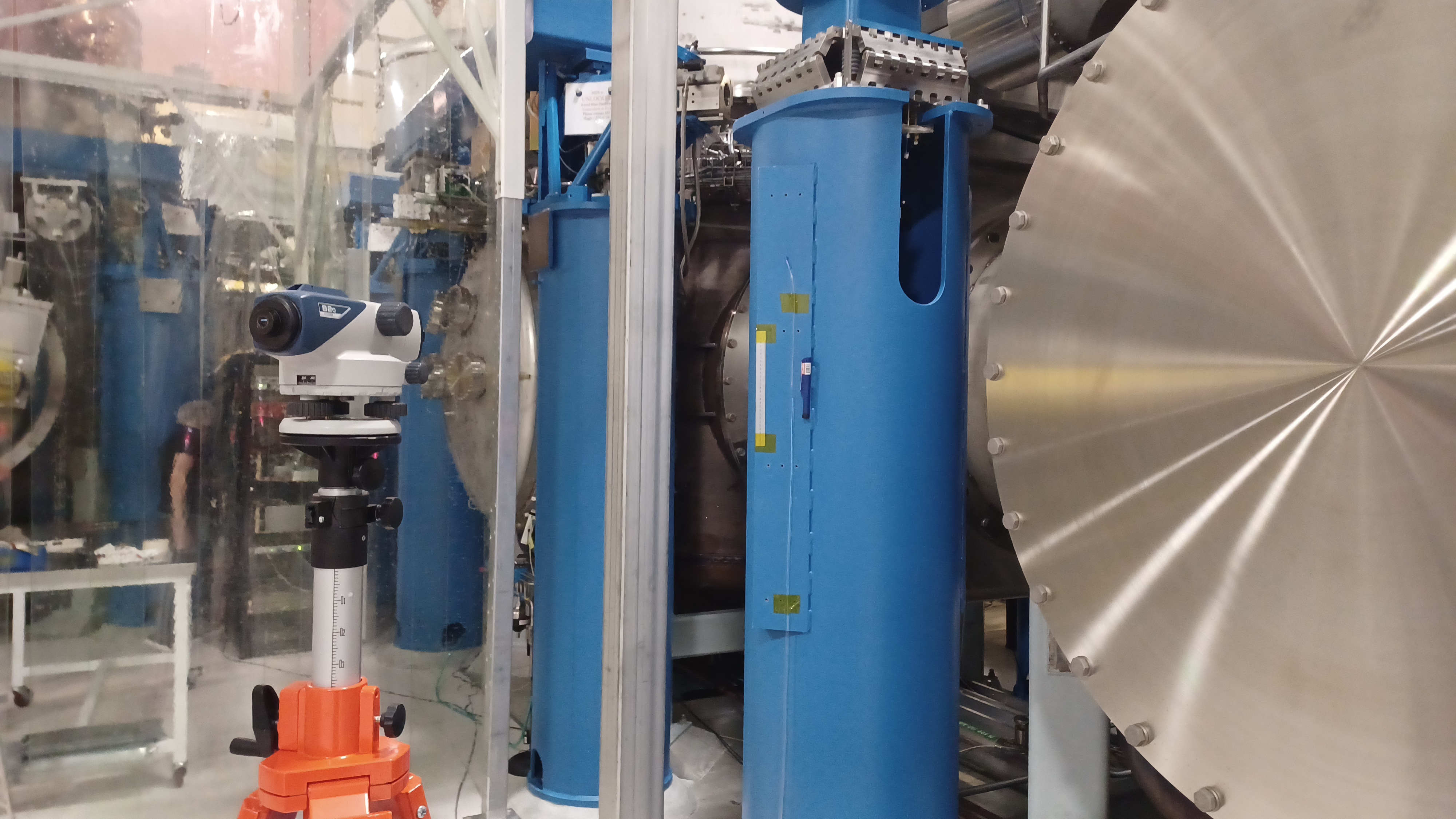
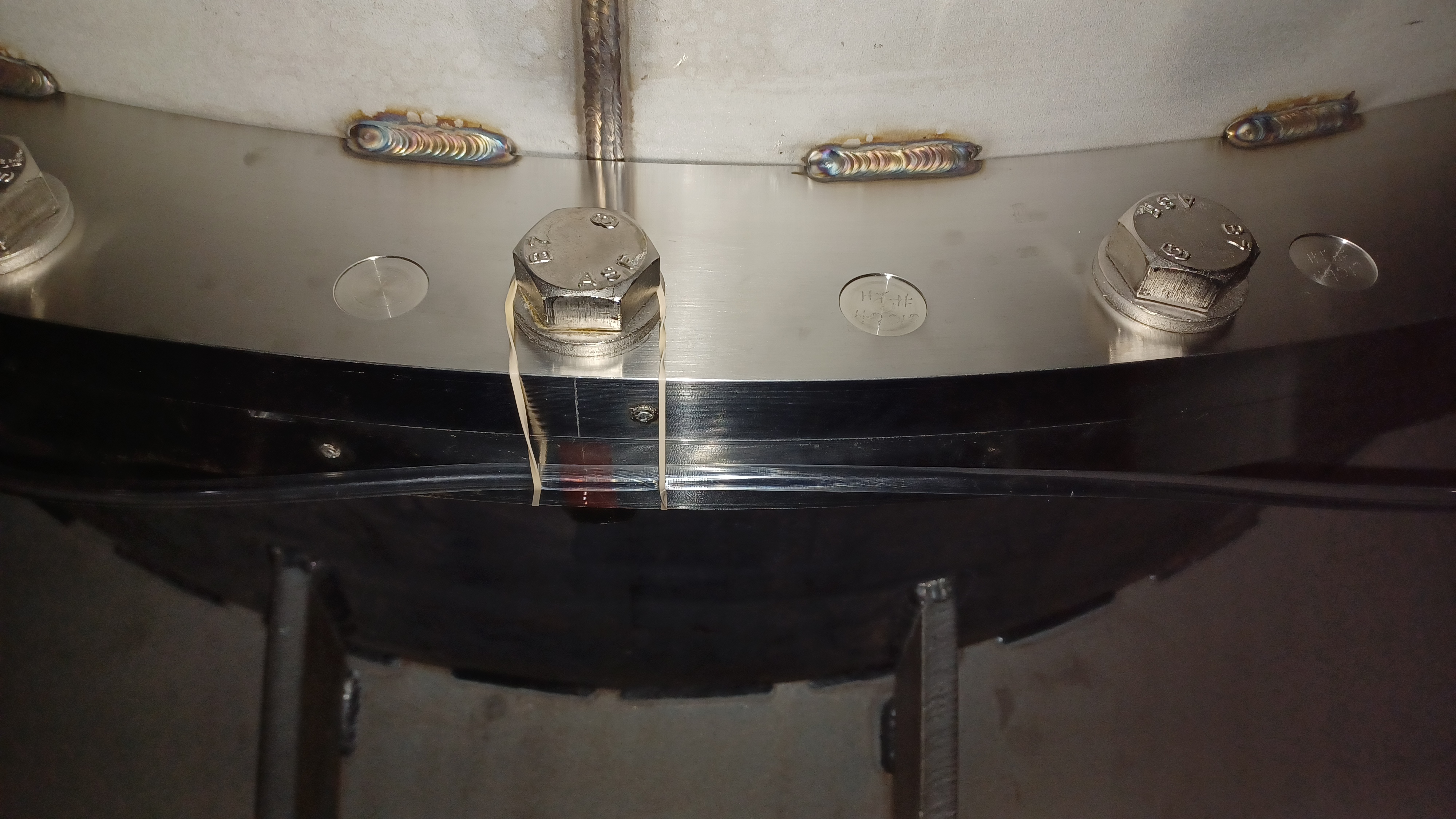
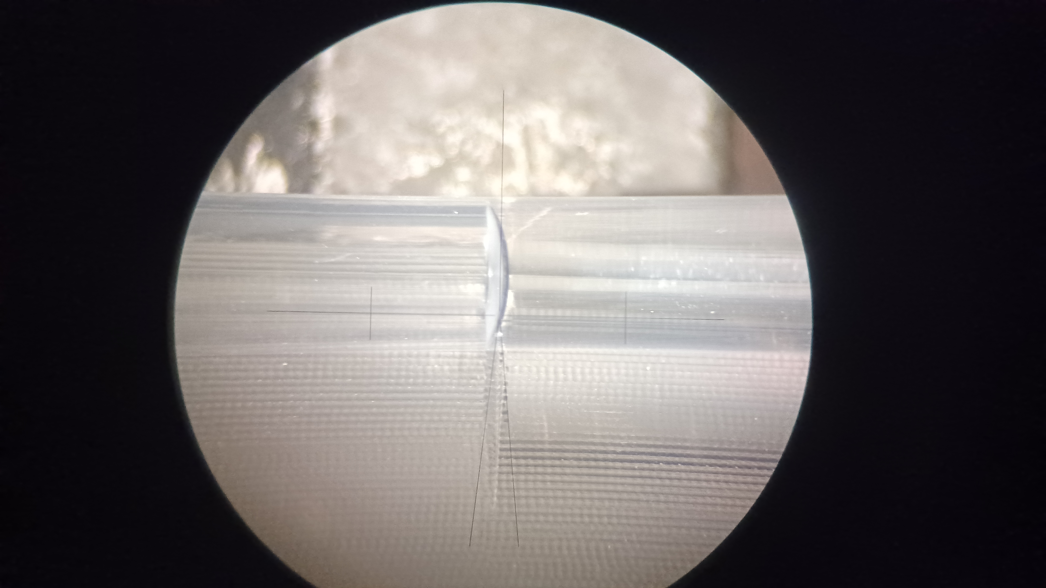
Based on the results of our FARO work detailed in alog 75771, we want attempt to re-establish Z=0. This was originally done by averaging the 8 door flange scribes of the BSC2 chamber (1 and 3 o'clock and 1 and 9 o'clock on each of the 4 door flanges). With all of the line of sight blockers (beam tubes, other chambers, electronics racks, cable runs, etc.) we felt the easiest way to repeat this was to use a water tube level. To do this we used roughly 60' of flexible tubing with an 8mm OD and 6mm ID. We filled it with water (setting up a siphon works great for keeping air bubbles out of the tube), leaving some air at each end, and set up around BSC2. One end of the level was fixed to the unused HEPI pier for BSC8, with a scale attached nearby for measurements; the other end was placed along the door flange scribe under measurement. We used an autolevel to set the water line on the scribe line to be measured, then used a 2nd autolevel to sight the other end of the tube and take a reading on the scale. We ended up using several rubber bands and some tape to secure the tube to the door flange; the tape was necessary to keep the tube from sagging under the weight of the water (the BSC scribes are over 6' above the ground), while the rubber bands helped to keep it mostly secure while we were setting it on a scribe line. The first 3 pictures show the setup, with the third one taken through an autolevel to show a close up of the water in the tube (have to sight at the bottom of the meniscus, just like with a graduated cylinder or similar measurement devices (like glass measuring cups in your kitchen)).
We did have a few issues, chief among them being that we could not get the water in the tube to stop moving at first. We would set the water line on a door flange scribe and watch it settle, and it would keep dropping slowly over several minutes. We noticed that regardless of where we set the water level, it would always drop to the same point; what finally clued us in to the issue was noticing that the other end of the water level was also dropping. If the level were rebalancing we would expect one end drop while the other raised, but this was not the case. At this point we also noticed that, even though we left about 12" of air at each end of the tube when we initially filled it, we now had almost 2' of air at each end. The solution? Not enough water in the tube, so add some more. We did this and all the stability problems vanished. We could then set the level on a scribe line, and after just a few seconds it would settle out and be very stable. Best explanation I have is we didn't have enough water to account for the slight compression of the water column at both ends of the level, since our measurement point was over 6' off the ground. With only a 6mm ID on the tubing, it doesn't take much to cause a big difference in how the level behaves. By adding ~9mL of water to the tube (using a 2mL transfer pipette) all of our problems were solved. Second issue, don't step on or touch the water level once set. This causes the water in the tube to move, a lot.
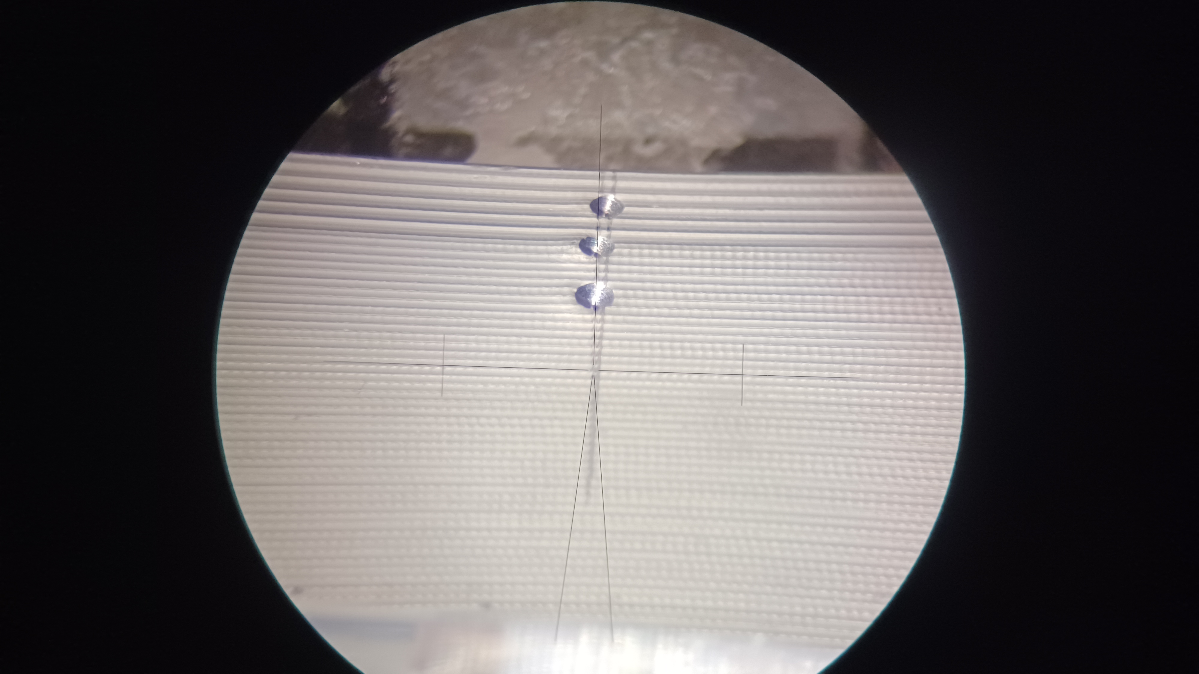
The other big issue we had is sighting the correct scribe line on the door flanges. Over the years since site construction several additional scribe lines have been added to many of the door flanges, all within several mm of each other. Most have no markings on them, a few had arrows, but 1 scribe on each flange was marked with 3 punch marks; this was also true for the 3 flanges with only 1 scribe on them. So we sighted the scribe line marked by the punches on all door flanges. The 4th picture shows an example of these punch marks (there are 2 scribe lines in this pictures, one that is straight and one that is not; we used the one that is straight, which can be seen behind the autolevel cross hairs).
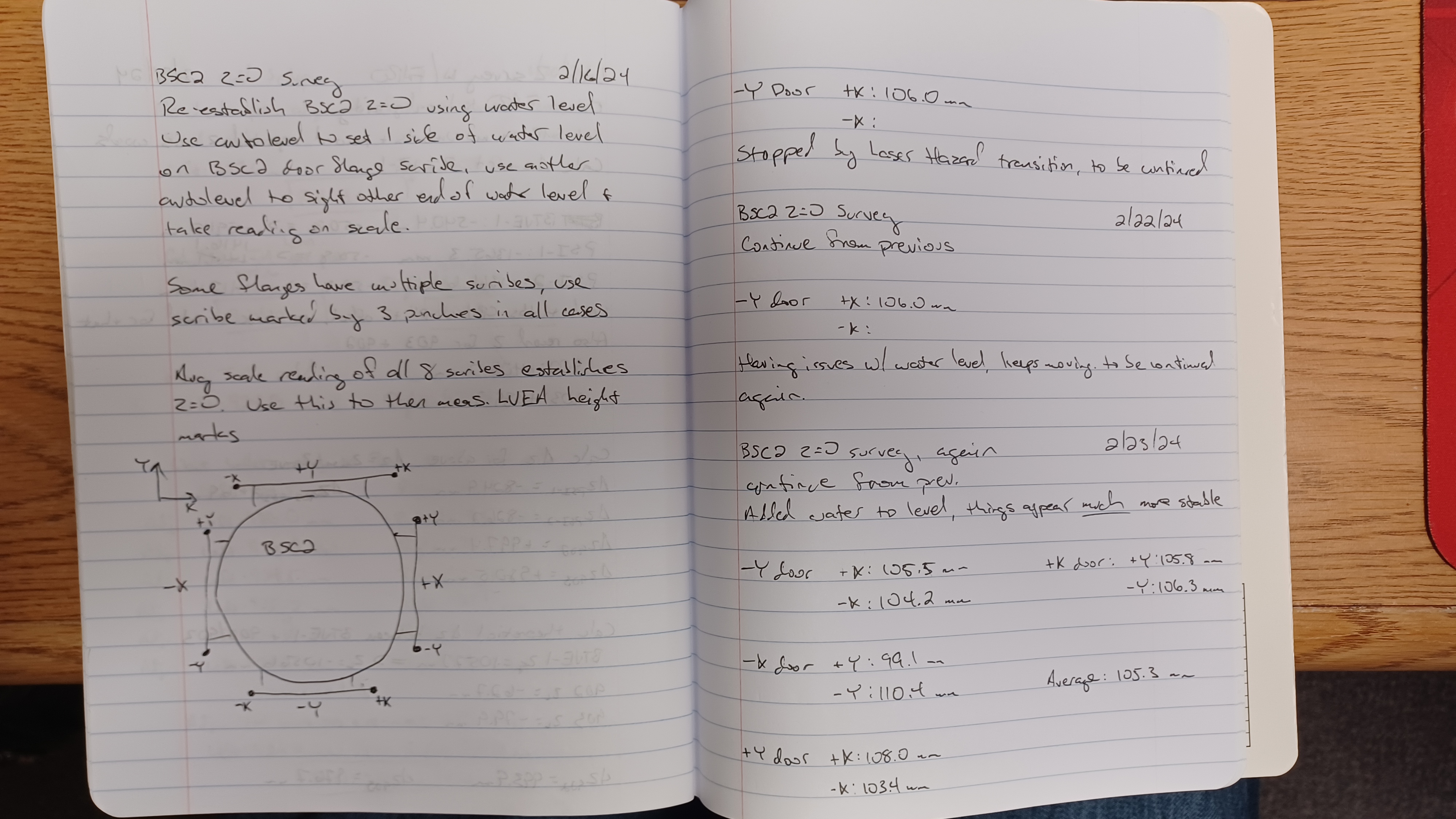
With our scribe lines chosen and other issues figured out, we set about measuring all 8 of the BSC2 door flange scribes. The final picture is a shot of my notes from the survey. Notice the large separation for the -X door scribes. Mike Zucker indicated to us that he thinks the scribes were placed to within +/- 1mm of flange center (having a hard time finding documentation of this, he is currently looking for the old "end item data package" for the chambers from their initial construction in the 90s), so this 11.3mm separation in particular is puzzling (we also measured a 4.6mm separation for the +Y door, 1.3mm separation on the -Y door, and 0.5mm separation on the +X door). One thing he suggested we can do is use a flat survey tape to check that the scribes are on a true diameter of the flange (are they 1/2 circumference apart?), which we will do once we have Laser Safe again. Once we confirm we've used the correct scribe lines we will continue with using the average of these scribes to check the various height marks around the LVEA. Should we find that we don't have the correct scribes then we will have to repeat the water level survey.

Tagging EPO for FARO pics.
J. Oberling, R. Crouch, R. Short
Ryan S. and I went out yesterday, 2/29, and used a flat survey tape to measure the distance between the 3-punch scribe marks along the circumference of the 4 BSC2 door flanges; the survey tape has 1.0 mm tick marks, so best we can measure to is the closest 0.5 mm. If these scribes are the correct ones to use then they should be 1/2 circumference from each other, which would mean the difference we measured with the water level are due to the flanges being clocked when the chamber was built. We had to do some DCC spelunking to find the correct OD for the BSC door flanges. Ryan C. found D970412, which eventually led to D961102. This document is the Release for Quote for the BSC door flanges, so not an as-built, but it's the best we've been able to find so far so I'm going with it. D961102-04.pdf lists the OD of the BSC door flange as 68.50 inches. Converting that to mm and calculating the 1/2 circumference gives us 2733.0 mm. Our measurements from yesterday:
- +Y door: 2732.0 mm
- -Y door: 2734.5 mm
- +X door: 2734.0 mm
- -X door: 2733.0 mm
So the 3-punch scribes on all door flanges meet the expected 1/2 circumference of 2733.0 mm to within +1.5/-1.0 mm. We have yet to find any kind of documentation or spec for these scribe lines, so I can't definitively say to what tolerance they were supposed to be placed to, but I've been told +/-2.0 mm in the past and our measurements appear to meet that. To me this says that Ryan C. and I used the correct scribe lines during our water level survey, but the flanges were unexpectedly clocked w.r.t. local horizontal. This in turn does give us an average across those 8 scribe lines that we can use to start measuring height marks to see if we can identify the source of the Z axis discrepancies the FARO has been reporting. Ryan C. and I will begin doing this during upcoming Tuesday maintenace windows as both of our schedules allow.