Reports until 02:10, Thursday 05 September 2013
H1 AOS
keita.kawabe@LIGO.ORG - posted 02:10, Thursday 05 September 2013 - last comment - 13:37, Thursday 05 September 2013(7629)
TMS initial alignment done (Corey, Cheryl, Doug, Jason, Keita)

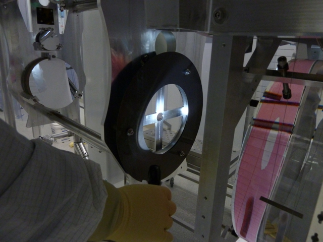
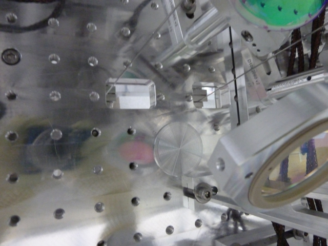
We're done with the initial alignment using the total station and the red laser. The final fine alignment should be done in chamber with ISCTEX in place.

Angle:

TMS yaw angle was adjusted by pushing the TMS SUS cube, and pitch by adjusting the sliding mass on the ISC table, such that the red laser beam from the total station is centered on the aperture on the ISC table. We used a small target placed in the aperture, but putting a target on the ISC table throws the PIT balance off. In the end we placed the second (dummy) target that is identical to the real target such that two targets are symmetrically placed around the center of the table.

Centering relative to ETM:

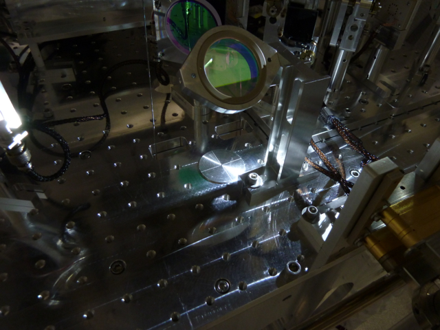
TMS centering relative to ETM was measured by the total station after putting the table/tele on the alignment stabilizing tooling such that the set screws barely touch the ISC table, then mounting the large target on the large input aperture of the telescope secondary plate.

TMS was 5 to 6mm lower than the ETM and off to the outside of L shape of the IFO by 1.5mm or 2 according to Jason. So the centering error is 

sqrt(6^2+2^2) = 6.3 mm

in the worst case.

This is very acceptable both for the green and IR beam.

Green:

Outside of the arm on the AR side of the ETM, the green arm mode has the waist radius of about 6mm, the Rayleigh range of about 200m, the divergence angle of about 6mm/200m=30urad, and the waist  is 1500m away from the ETM into the arm (see e.g. T1200200).

If we inject a beam from the center of TMS (6.3mm offset from the arm mode at the ETM) such that there's no lateral displacement at the waist, the misalignment angle would be 6.3mm/1500m = 4.2urad.

The power mismatch would be (4.2urad/30urad)^2 = 2%. This is nothing.

IR:

The requirement for the centering tolerance for the IR beam is much larger than the green, as the only important thing for IR is that both of the QPDs will see the light. Even if the IR beam is half radius off of the center of the QPDs that would be OK. Having said that, just for the completeness I'll show some numbers.

Outside of the arm on the AR side of the ETM, the IR arm mode has the waist radius of 8mm, the Rayleigh range of 200m (same as green), divergence angle of about 40urad,  and the waist is 1500m away from the ETM into the arm.

If the TMS is aligned as described above (no lateral displacement at the waist but 6.3mm offset at the ETM) the power mismatch parameter would be (4.2/40)^2=1%. 

Comments related to this report
cheryl.vorvick@LIGO.ORG - 13:37, Thursday 05 September 2013 (7635)
Pictures:

Pictures 1 and 2 - IAS alignment targets, as used for IAS alignment ------------------------

NOTE: each target required illumination with a flashlight, however, the picture of the small target was erroneously taken illuminating the target from the top when it needs to be illuminated from the bottom of the ISC table.


Pictures 3 and 4 - Cables rerouted above the upper mass ------------------------

These two pictures show that with cable ties, rerouting cables, and changing peek clamp locations on the ISI, the cables coming through the upper mass are no longer touching the upper mass.

Cable ties were used to tension the 4 cables in such a way that they curve away from the cable clamp in the center of the upper mass as they exit through the top of the upper mass.  

Originally the two thicker cables coming from the center of the upper mass were routed in the +X direction and the two thinner cables were routed in the -X direction when exiting the upper mass.  This configuration was swapped so thicker cables are now routed in the -X direction, and thinner cables in the +X direction.  

Inside the upper mass, the thicker cables are on the -Y side of the clamp, and the blades above the upper mass are positioned so that there is more space on the ISI in the -X,-Y direction above the upper mass.  This meant that routing the thicker cables in the -X direction allowed Keita to pull the thicker cables farther in the -Y direction with the peek clamp on the ISI,  and allowed the thinner cables to clear the upper mass.


Pictures 5 and 6  - IAS alignment targets, as used for a rough balancing the table ------------------------

Picture 5 is the small target installed on the table.  This is used to center the red alignment beam (from the IAS total station) as it goes through the ISC table from the telescope.  View the red beam on the underside of the target/ISC table.

Picture 6 is the spare small alignment target positioned on the table to balance out the effect of the real target.  Not quite positioned relative to the wires in the same way as real target, but significantly better than not having it there, and good enough for testing and as a starting point after the flight into the chamber.

Images attached to this comment