jeffrey.kissel@LIGO.ORG - posted 15:55, Wednesday 13 March 2024 - last comment - 13:22, Thursday 19 September 2024(76352)
On Filling out the new ETM and TMS Watchdog Infrastructure to Produce the Sensible, Calibrated, BLRMS signal for triggering
J. Kissel, O. Patane
A follow-up from yesterday's work on installing the infrastructure of the upgrades to the ETM and TMS watchdog systems, in this aLOG I cover with what I've filled out the infrastructure in order to obtain the calibrated BLRMS that forms the trigger signal for the user watchdog.
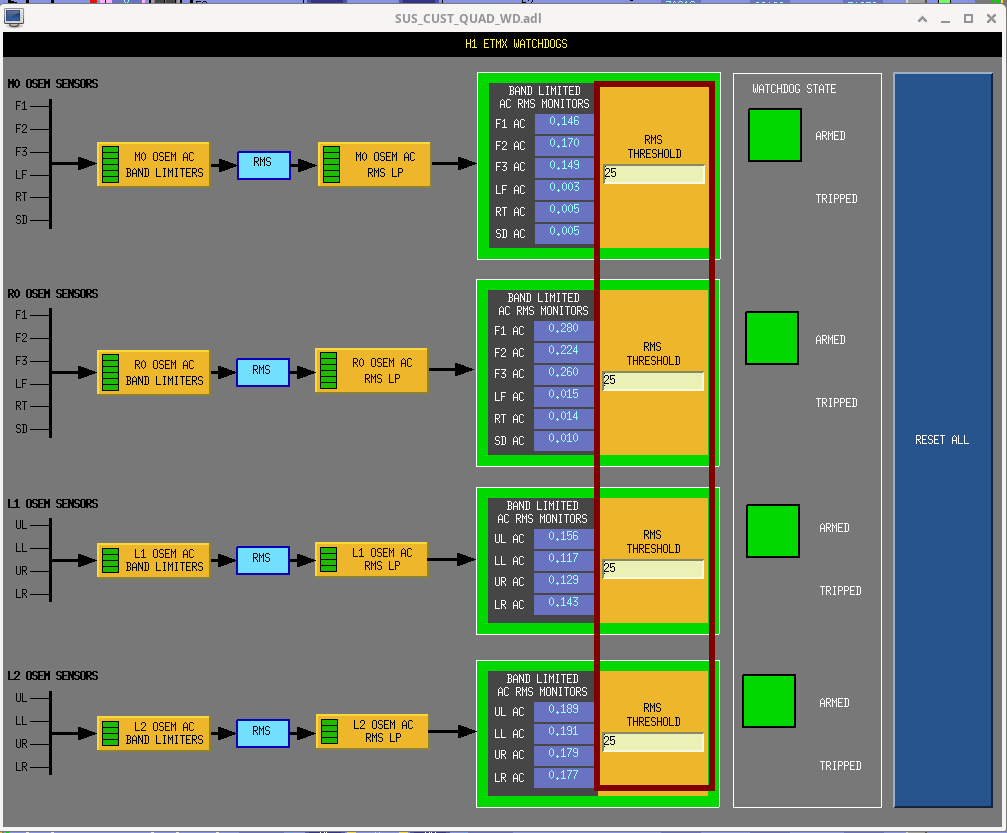
Remember, any sensible BLRMS system should
(1) Take a signal, and filter with with a (frequency) band-limiting filter, then
(2) Take the square, then the average, then square root, i.e. the RMS, then
(3) Low-pass the RMS signal, since only the "DC" portion of the RMS has interesting frequency content.
As a bonus, if your signal is not calibrated, then you can add
(0) Take the input to the band limiting filter, and calibrate it
(and through the power of linear algebra, it doesn't really matter whether you band-limit first and *then* calibrate)
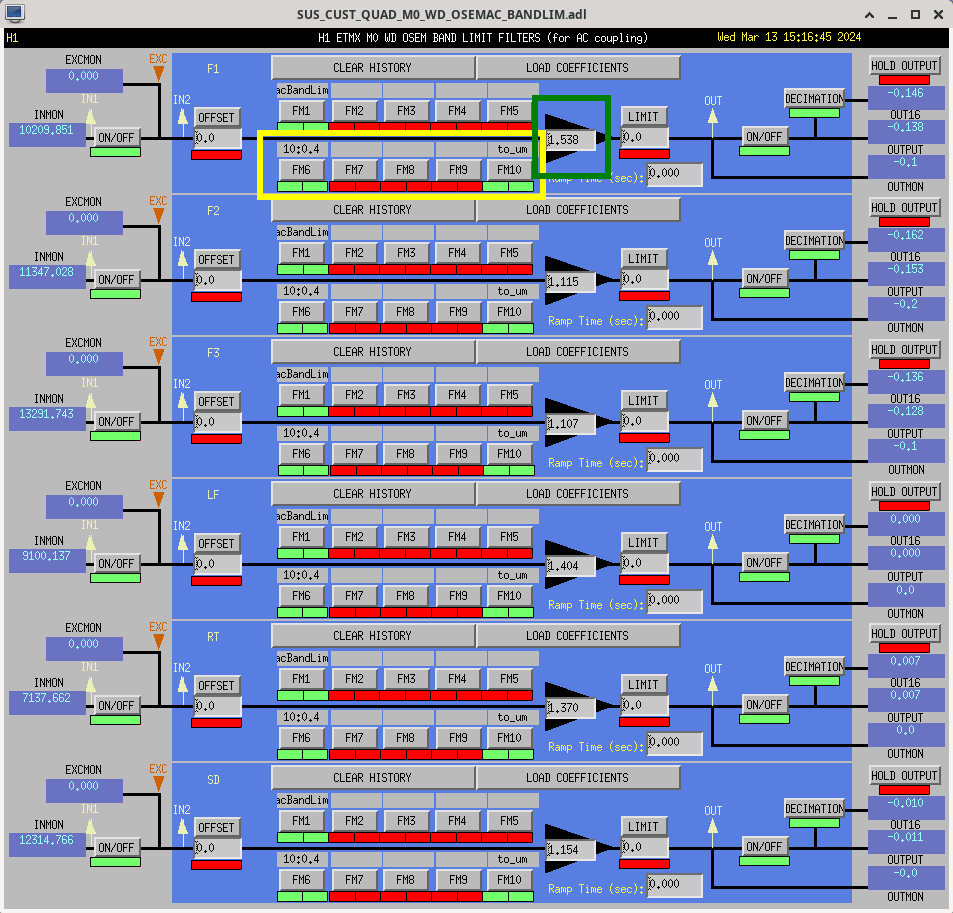
This screenshot shows the watchdog overview screen conveying this BLRMS system.
Here're the details of the BANDLIM and RMSLP filters for each of the above steps:
(0) H1:SUS-ETMX_??_WD_OSEMAC_BANDLIM_??
FM6 ("10:0.4") and FM10 ("to_um") are exact copies of the calibration filters that are, and have "always been" in the OSEMINF banks. These are highlighted in the first attachment in yellow.
FM6 :: ("10:0.4") :: zpk([10],[0.4],1,"n") :: inverting the frequency response of the OSEM satellite amp frequency response
FM10 :: ("to_um") :: zpk([],[],0.0233333,"n") :: converting [ADC counts] into [um] assuming an ideal OSEM which has a response of 95 [uA / mm], differentially readout with 242 kOhm transimpednance and digitized with a 2^16 / 40 [ct / V] ADC.
In addition, I also copied over the GAIN from the OSEMINF banks and copied these over as well such that each OSEM trigger signal remains "normalized" to an ideal 95 [uA / mm] OSEM. These are highlighted in dark green in the first attachment.
(1) H1:SUS-ETMX_??_WD_OSEMAC_BANDLIM_??
FM1 :: ("acBandLim") :: zpk([0;8192;-8192],[0.1;9.99999;9.99999],10.1002,"n") :: 0.1 to 10 Hz band-pass
(2) This is a major part of the upgrade -- the front-end code that does the RMS was changed from the nonsense "cdsRms" block (see LHO:1265) to a "cdsTrueRMS" block (see LHO:19658)
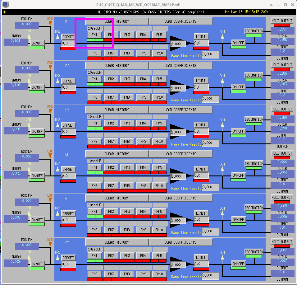
(3) H1:SUS-ETMX_??_WD_OSEMAC_RMSLP_??
FM1 :: ("10secLP") :: butter("LowPass",4,0.1) :: 4th order butterworth filter with a corner frequency at 0.1 Hz, i.e. a 10 second Low Pass.
This is highlighted in magneta in the second attachment. These are direct copies from other newer suspension models that had this infrastructure in place.
I've committed the filter files to the userapps repo,
/opt/rtcds/userapps/release/sus/h1/filterfiles/
H1SUSETMX.txt
H1SUSETMY.txt
H1SUSETMXPI.txt
H1SUSETMYPI.txt
H1SUSTMSX.txt
H1SUSTMSY.txt
are all committed as of rev 27217.
All of these settings were captured in each model's safe.snap. I've not yet accepted them in the OBSERVE.snaps.
Images attached to this report
Comments related to this report
Here's a handy script that demos using the python bindings to foton in order to easily populate simple filters from a python script.

I've only used this from the control room workstations, whose environment has been already built up for me, so I can't claim any knowledge of details about what packages this script needs. But, if you have the base cds conda environment this "should work."
Non-image files attached to this comment
