EvanH, FranciscoL
Because we've been loosing lock for unknown reasons, we measured OLG transfer function of MICH, SRLC, and PRLC. The UGF for each one is (see attached figures for reference) roughly
MICH: 10 Hz
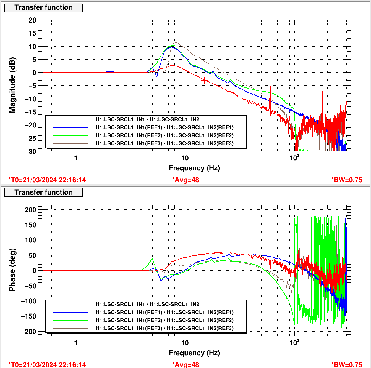
SRCL: 12 Hz
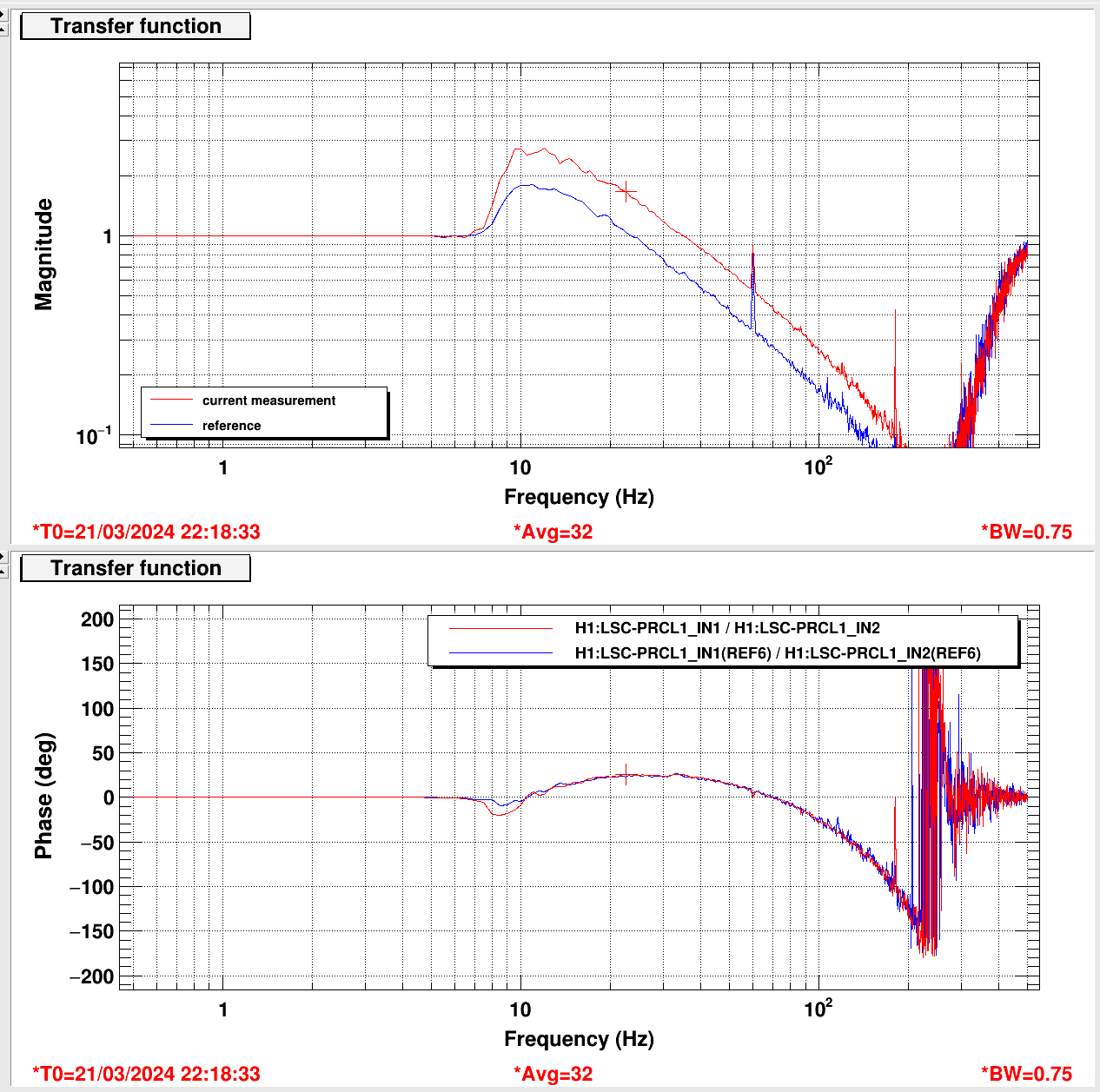
PRCL: 35 Hz
We may want to lower the MICH UGF to avoid cross coupling with the SRCL loop.
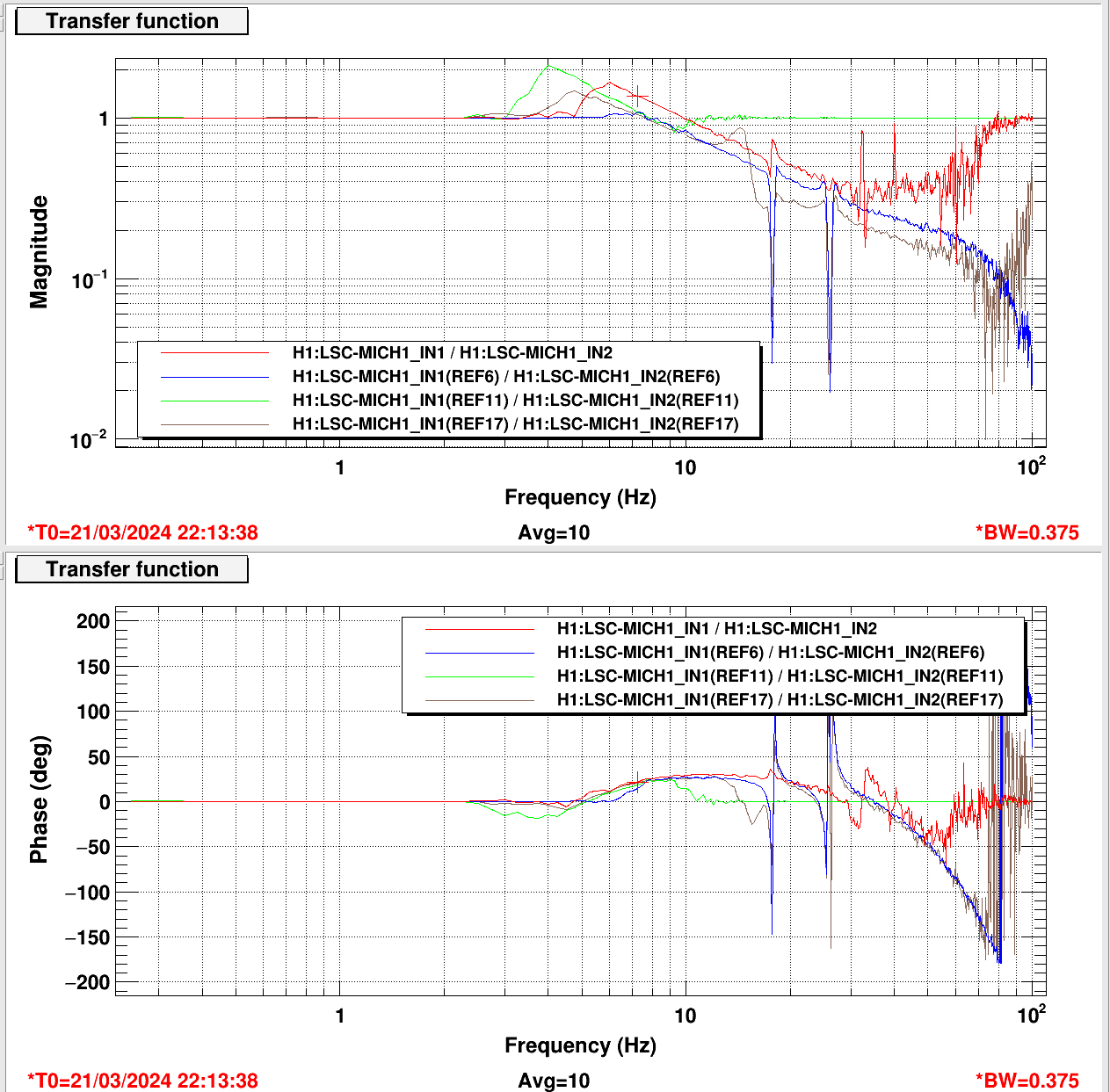
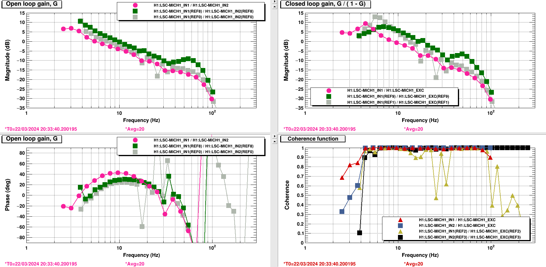
The Michelson loop is probably showing a cross-coupling with either PRCL or SRCL. The attachment shows a hump in the OLTF around 60 Hz that scales nonlinearly with overall loop gain changes. Green is the current situation, with the UGF close to 10 Hz, which is also where the SRCL UGF is.
Recall that we had previously reduced the Michelson UGF and applied some antiboosting, but this was reverted during higher-power operation. I am now more or less restoring this reduced UGF operation (UGF 5.5 Hz, antiboosting that amounts to 6 dB less gain below 1 Hz). This uses LSC-MICH1 FM8. The new OLTF is pink in the attachment.
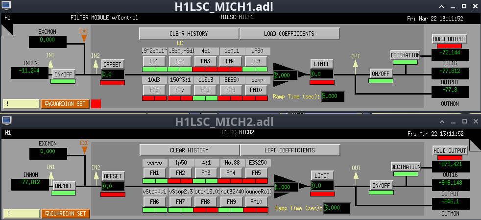

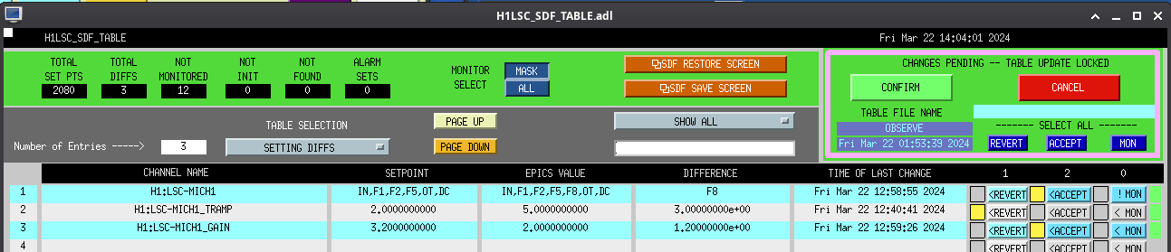
SDFs in OBSERVE.snap table on the LSC model following Evan's work. New filter and gain accepted, ramp time reverted.
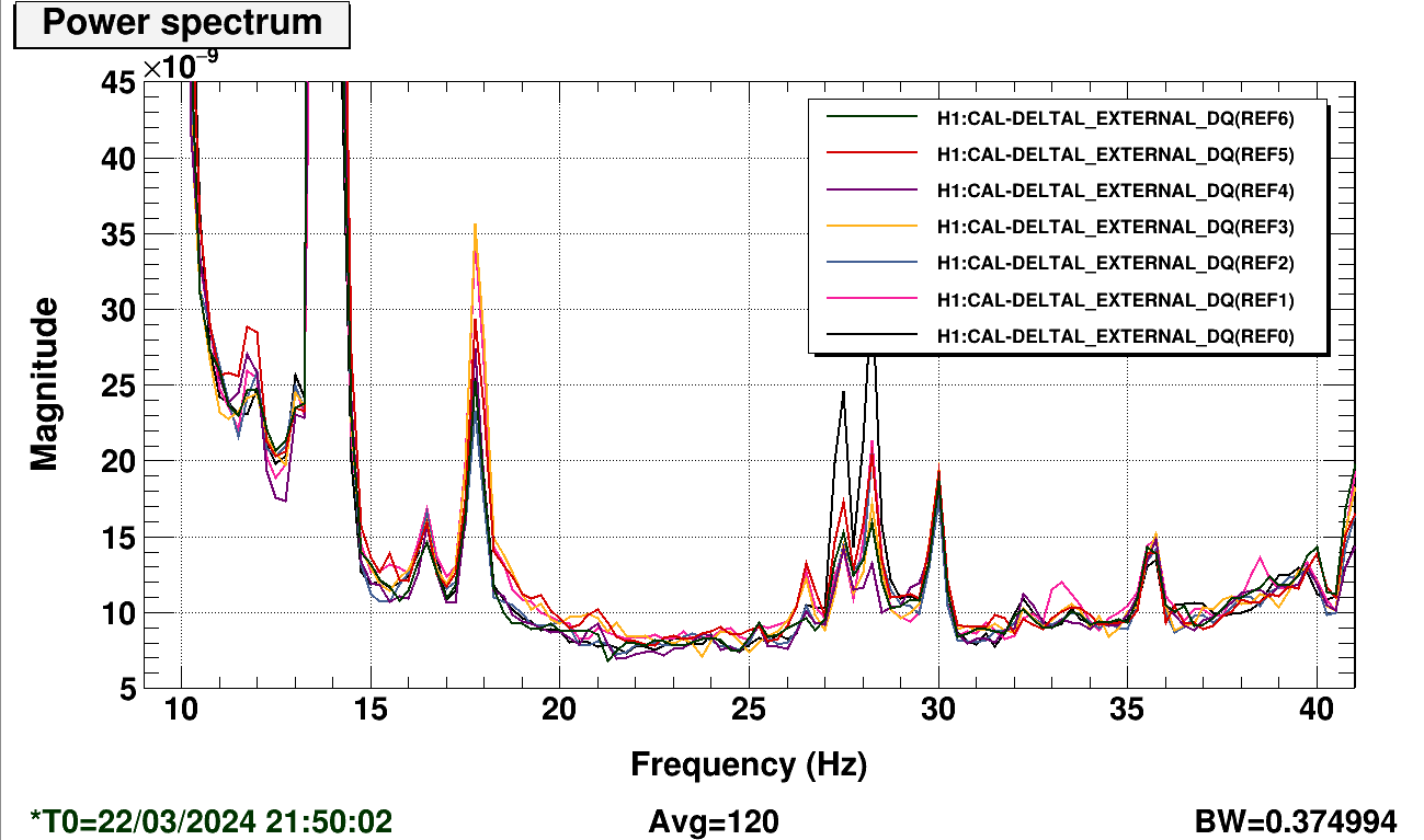
On/off testing shows some mild improvement in the 18–23 Hz region, possibly because of less drive around the BS bounce mode. We may want to re-engage the bounce/roll notches in this length loop.
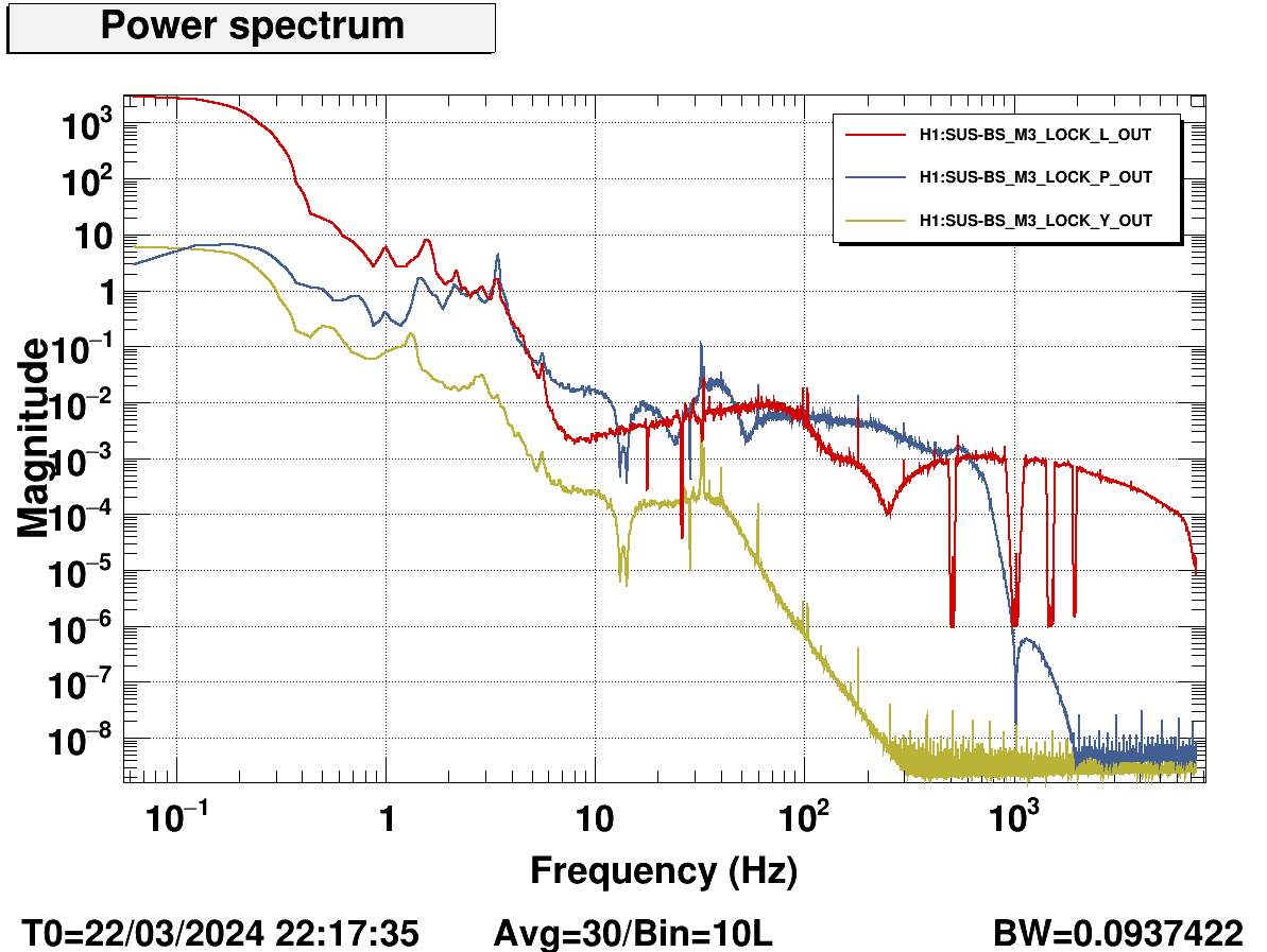
Also, it seems like the drive to the BS coils above 10 Hz is actually dominated by pitch drive. Someone may want to redo the plant inversion for the ASC-MICH_P loop, as it appears to be much more aggressive than the yaw loop.
Regarding the ASC MICH P drive, I was looking into updating the filter and realized there is a sneaky 17 Hz low pass filter on BS M2 Lock P and Y. Gabriele and I did not take this filter into account when redesigning the MICH ASC filters (69370). Just adding this additional filter into the model shows quite a bit of gain peaking around 3 Hz. I'm not sure if that's actually the big problem here, but clearly this could use a redesign. I'll work on it, and also check the MICH Y control design.
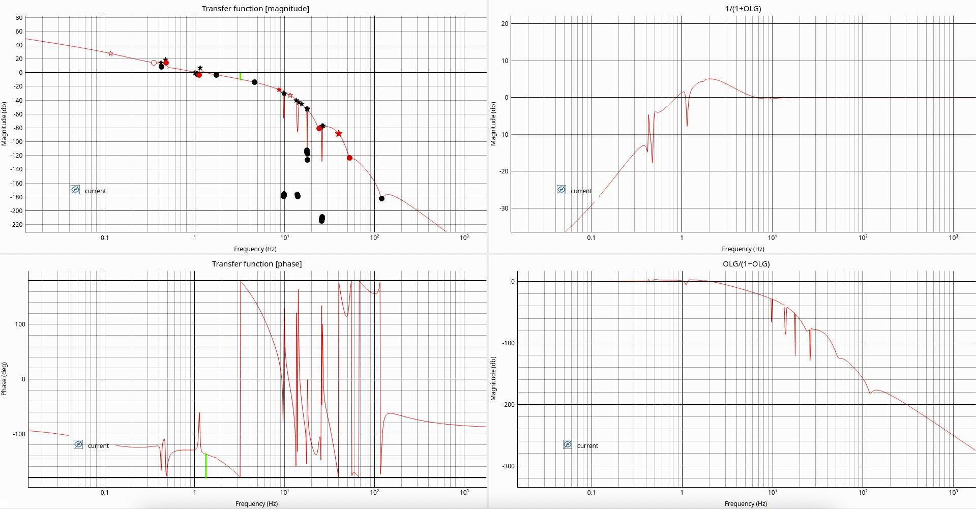
Edit: actually, that might not be that much of a problem after all. We could probably improve some low frequency suppression, but I don't know how much we can reduce the pitch drive above 10 Hz. After correcting the model according to my measurement in 72117, there is not much gain peaking and a good amount of phase and gain margin. Yes, the plant inversion is aggressive, but it seems to be working. Attached a screenshot from Gabriele's loop designer code, where I have implemented the BS M2 pitch model, BS M2 locking filters, and current ASC MICH P control design. Black dots/stars in the top left plot are the Zs/Ps of the plant model and locking filters, red dots/stars are the Zs/Ps of the control loop filters. The UGF is around 1 Hz as I measured, and there is 5 dB of gain peaking at 2 Hz (top right plot).