Naoki, Vicky, Jennie W
Naoki followed the directions in to set up the SQZ beam OMC scan.
We had a problem with the DC centering loops. After we switched them on they saturated the OM1 and OM2 suspensions.
We got around this by switching each of the 4 degrees of freedom on first - ie. DC3 Y, DC3 P, DC4 Y, DC4 P.
Then we engaged OMC ASC and this seemed to work ok.
When we tried to manually lock the OMC length loop we had problems as when we switched the gain of 1 on it would lose lock, even when on a TM00 mode of the expected height (0.6mA on DCPD_SUM).
Vicky got around this this using a lower gain and not engaging the BOOST filter in the servo filter bank.
Then she had to touch up the alignment in lock with OM3.
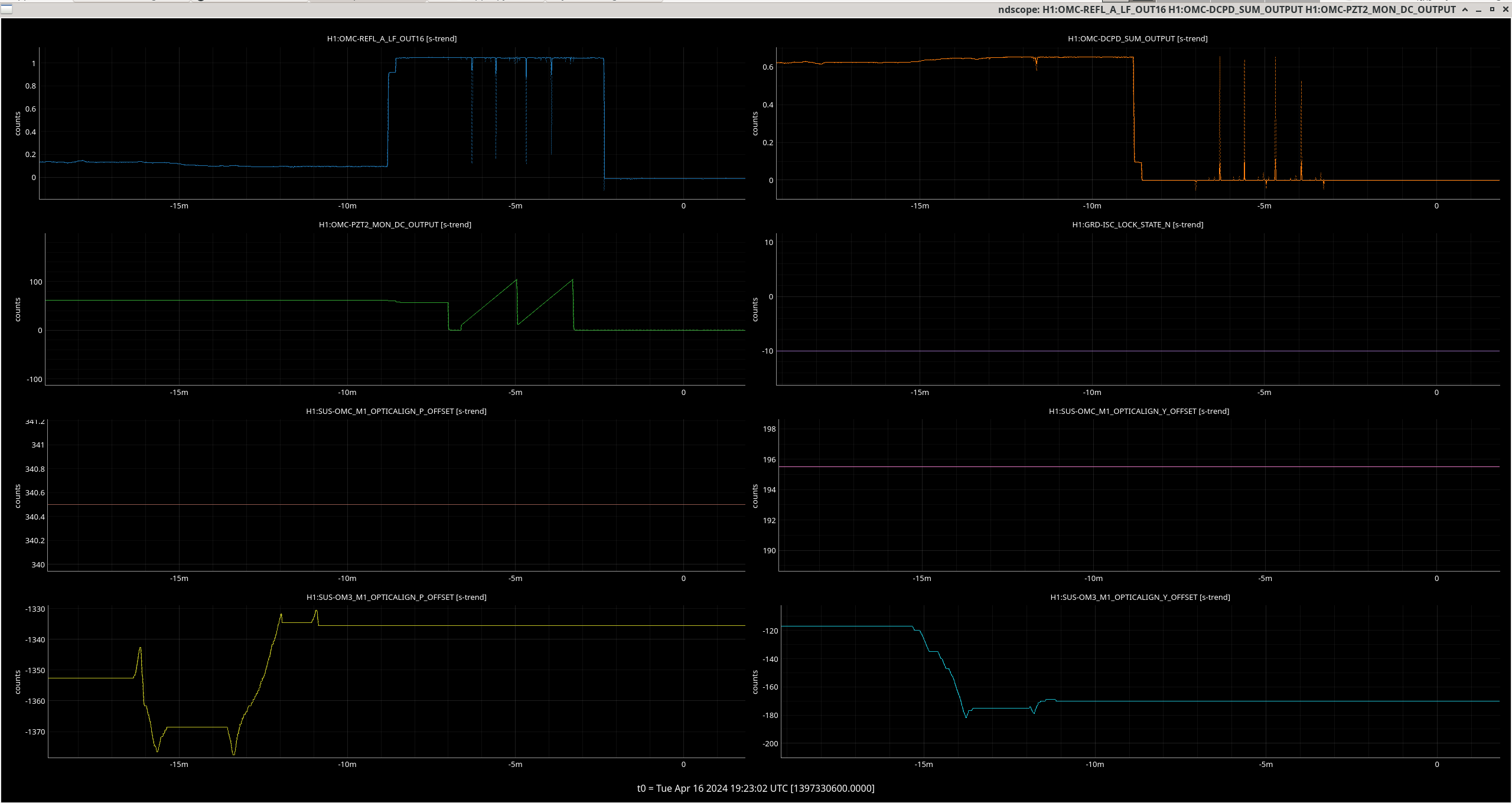
locked quiet time 1397329970 GPS 1 min:
OMC-REFL_A_LF_OUT16 = 0.0930255 mW
OMC-DCPD_SUM_OUTPUT = 0.652156 mA
unlocked quiet time 1397330106 GPS 1 minute:
OMC-REFL_A_LF_OUT16 = 1.04825 mW
OMC-DCPD_SUM_OUTPUT = -0.00133668 mA
dark measurement 1397330625 GPS 1 minute:
OMC-REFL_A_LF_OUT16 = -0.0133655 mW
OMC-DCPD_SUM_OUTPUT = -0.00133668 mA
I noticed after I took the dark measurement that OM1 and 2 were staurating again and need to clear history twice on OM1 to remove this.
Reverted OM1 and 2, 3 OMC sliders at 8:33 am (local time) on the 16th April.
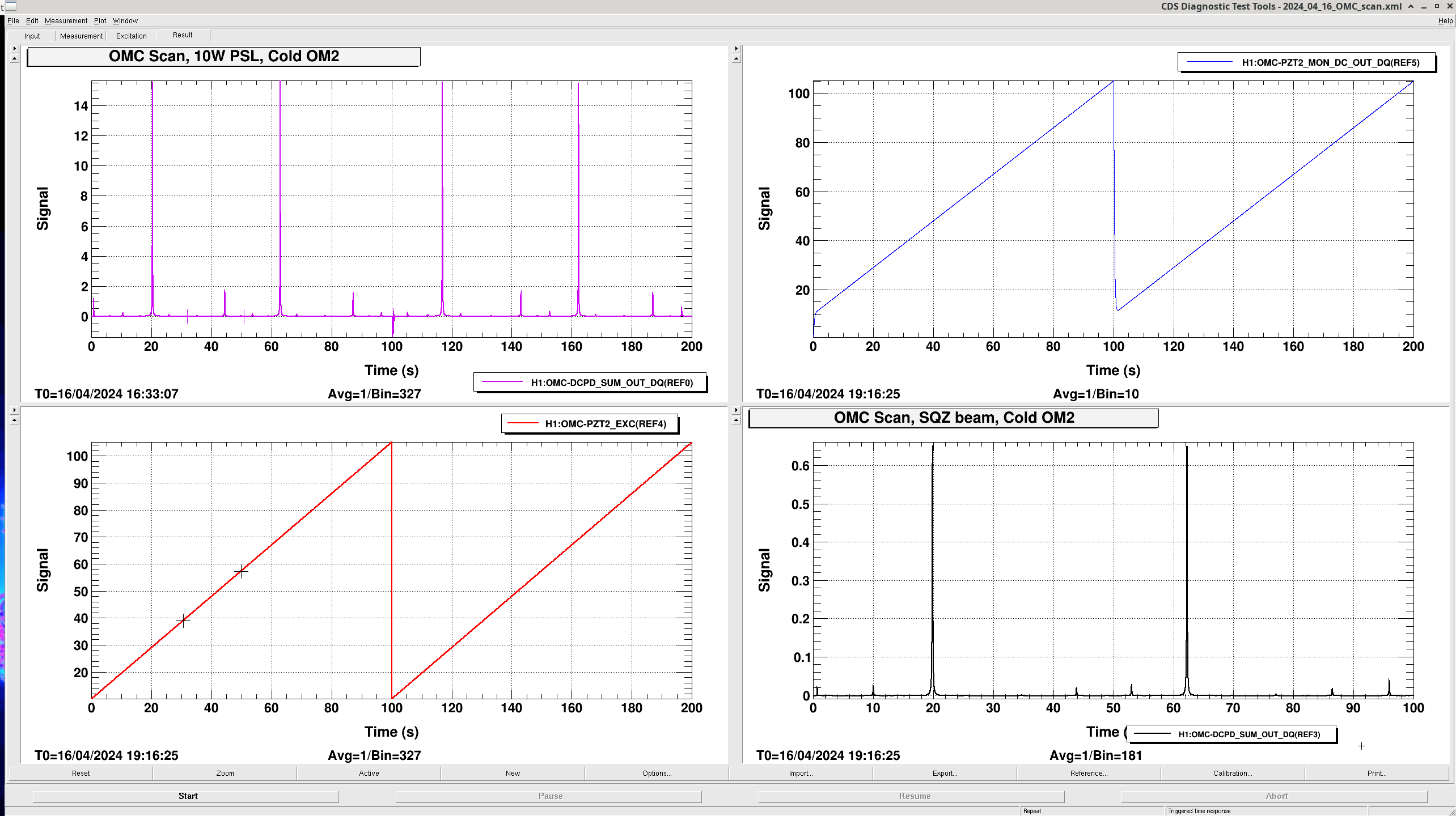
Data is saved as REf 3, 4 and 5 in /ligo/home/jennifer.wright/Documents/OMC_scan/2024_04_16_OMC_scan.xml. Where 3 is the scan channel OMC-DCPD_SUM_OUT_DQ on the bottom right plot, 4 is the PZT excitation channel OMC-PZT2_EXC on the bottom left plot, and 5 is the monitor of the actual PZT output voltage OMC-PZT2_MON_DC_OUT_DQ on the top right plot.
Using Sheila's code from this entry and updating the code with the current OMC values for transmission of the mirrors:
Tio = 7670e-6 #according to T1500060 page 116 input and output mirror transmission
R_inBS = 1-7400e-6
The outout of the code gives us the following values for the cavity incident power, efficiency and finesse:
Power on refl diode when cavity is off resonance: 1.062 mW
Incident power on OMC breadboard (before QPD pickoff): 1.078 mW
Power on refl diode on resonance: 0.106 mW
Measured effiency (DCPD current/responsivity if QE=1)/ incident power on OMC breadboard: 70.5 %
assumed QE: 100 %
power in transmission (for this QE) 0.760 mW
HOM content infered: 8.748 %
Cavity transmission infered: 77.827 %
predicted efficiency () (R_inputBS * mode_matching * cavity_transmission * QE): 70.493 %
omc efficency for 00 mode (including pick off BS, cavity transmission, and QE): 77.251 %
round trip loss: 2063 (ppm)
Finesse: 362.923
I need to compare the HOM content measurement with that derived from the mode scan.
Just realising now that I need this data that I never posted the results of the OMC scanm with this squeezed beam for the ZM4 = 120, ZM5 = 137 PSAMS settings.
The analysis was run with /labutils/omc_scan/fit_two_peaks_no_sidebands10.py and the function this uses to fit the whole scan is OMCscan_no_sidebands10.py, this code is in the /ligo/gitcommon/labutils/omc_scan repository but in the dev branch.
The first graph shows the full scan, the second zoomed in on the fit for the CO2 mode, since the astigmatism in our OMC is too small to resolve the two modes this fit has less value than with the old OMC.
To work out mode-matching it is probably enough to use the C02 height from the data and not the fit.
