J. Oberling, T. Guidry, R. Crouch
Progress since our last update.
When we ended last, we had large Z axis deviations for our PSI monuments that we speculated was due to the fit being unable to pick up on the tilt of the X axis in our global coordinate system, since the height marks we were using for Z axis alignment were all in a line along the Y axis. To test this, we decided to try aligning the FARO in the local LVEA coordinate system, then translating that alignment to our global coordinate system. We first tried this on 4/9/2024, then again with a slightly different method today, 4/16/2124.
4/9/2024
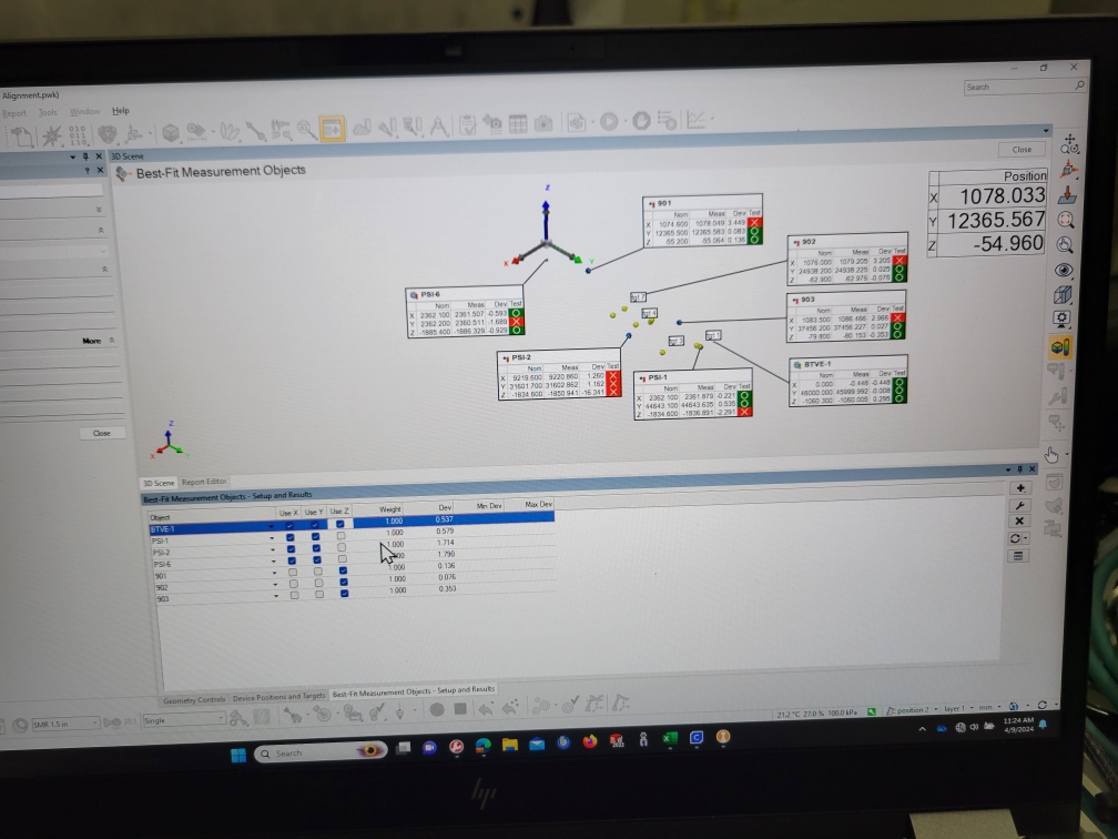
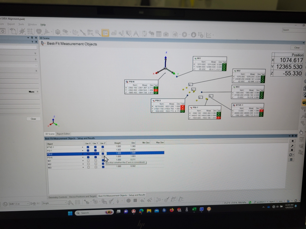
We first tried assuming the LVEA is perfectly flat; in other words, we used the same Z axis coordinate for all PSI monuments. With a new Z axis coordinate for BTVE-1 (-1060.3 mm) that we tied back to BSC2 Z=0, and our differential height measurement from alog 75669, we calculated a new Z axis coordinate for PSI-1 of -1885.4 mm. We then used this Z axis coordinate for PSI-2 and PSI-6 to give us a very rough Z axis alignment. We then followed the same method we used in alog 76889 to align the FARO, except we did not convert the Z axis coordinates to our global coordinate system, we left them in LVEA local. In the end, we were using BTVE-1, PSI-1, PSI-2, and PSI-6 for X and Y axis alignment, and BTVE-1, 901, 902, and 903 for Z axis alignment. At first we thought this looked pretty good, but then we noticed that we had some significant deviations in X axis coordinates for 901, 902, and 903 that were not there before we finalized the alignment. Turns out that excluding PSI-2 from the Z axis alignment drags everything off in X by several mm, and the alignment is still incapable of accurately resolving a Z coordinate for PSI-2 (16.3 mm deviation!). It's almost like the PolyWorks alignment algorithm thinks PSI-2 is rotated/tilted somehow w.r.t. the other monuments, we really don't have an explanation for it. This can be seen in the 1st 2 attached pictures. Regardless, it seems like this isn't the route to go down, so we ended the day at this point. Also, the maintenance window was almost over so we had to shut things down anyway.
Before completely shutting down, we did try converting from the local coordinate system to the global one. PolyWorks allows the user to set a new coordinate system by several methods, most importantly to us by translation and rotation about known axes. In other words, we can set a new Cartesian coordinate system, and translate and rotate it however we need. This is good for our purposes, as we can enter the rotation of our X and Y axes that converts from LVEA local to site global. Recall that, if you are sitting at the origin of the IFO's coordinate system, the global X axis is tilted down by 619.5 µrad w.r.t. the local LVEA X axis and the global Y axis is tilted up by 12.5 µrad w.r.t. the local LVEA Y axis. PolyWorks uses axis tilt as a roll of the axis, so we enter the Y axis tilt as an X axis roll and the X axis tilt as a Y axis roll (we don't translate the axes at all, the origins are supposed to be the same spot). This all seemed to go smoothly, but left a few things that we didn't have time to dig into: It looked like the rotation of the X and Y axes also induced a rotation of the Z axis, even though that is supposed to be held constant, and it looked like it was rotating too much (our Z axis coordinates changed more than we expected). More to look into for next time.
Speaking of next time...
4/16/2024
Today we essentially did a repeat of last week, except we did not assume the LVEA was perfectly level. Since we had the previous differential height measurements and the new BTVE-1 local Z axis coordinate, we used the differential height measurement data to calculate new LVEA local Z axis coordinates for PSI-1, PSI-2, and PSI-6. It should be noted that we weren't really in love with way we had to do the differential height measurement for PSI-6, due to line of sight issues, so we entered that as a placeholder only, it was not included in any alignments. To keep things consistent we used sphere features for BTVE-1, PSI-1, PSI-2, and PSI-6; this means we also included the correction for the sphere-fit rod, which measures the bottom of the monument punch and not the monument surface that the coordinate is registered to. The new LVEA local Z axis coordiantes we used today, properly corrected for punch depth, are:
- BTVE-1: -1061.1 mm
- PSI-1: -1886.5 mm
- PSI-2: -1887.3 mm
- PSI-6: -1881.9 mm (placeholder only!)
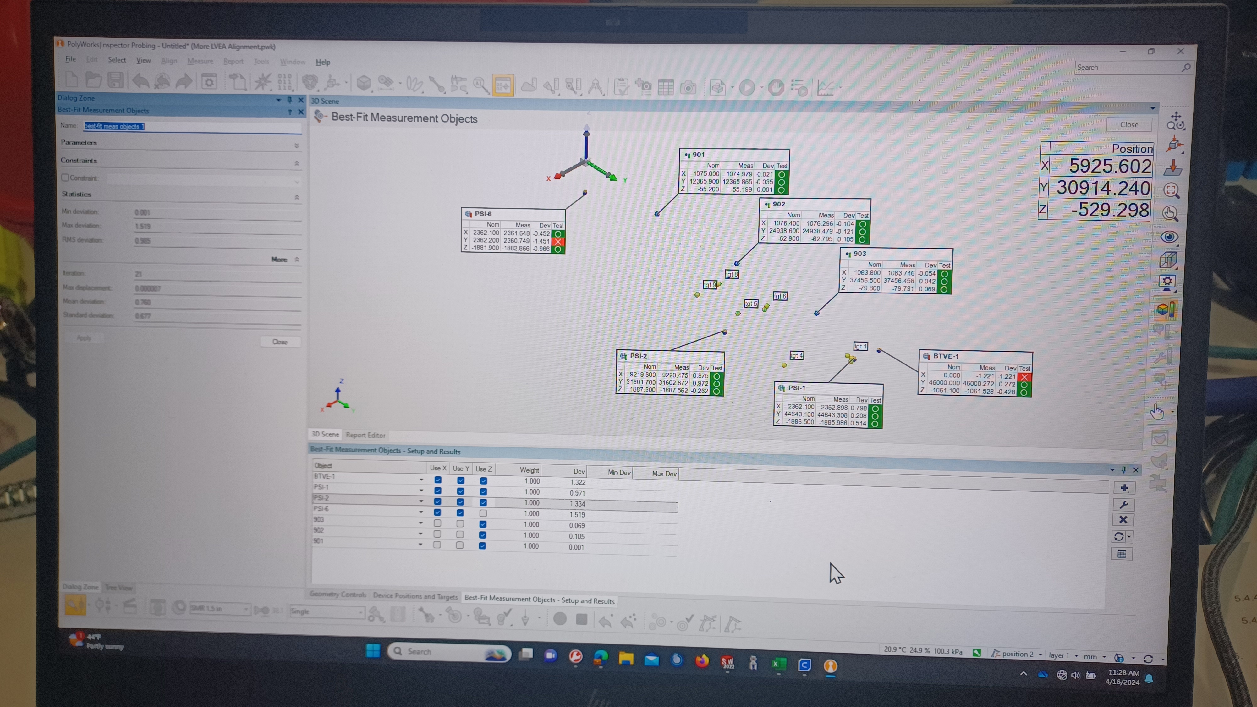
Since these Z axis coordinates for PSI-1 and PSI-2 are ones we directly measured with the FARO, via differential height measurement w.r.t. BTVE-1, and have tied back to BSC2 Z=0, via our water tube level survey and differential height measurements, we also included them in the alignment routine; as stated previously PSI-6 was excluded from the alignment routine as we do not trust that number. Following the same method previously used, we measured the X and Y coordinates for height marks 901, 902, and 903, and used our previously-measured Z axis coordinates from our water level survey. The results of the final alignment routine are shown in the 3rd attachment; this is in the LVEA local coordinate system. This is the closest we've yet been to something that looks like a good alignment to one of our coordinate systems (LVEA local in this case). One thing we immediately notice, the measured X axis coordinate for BTVE-1 is reported as off by -1.2 mm. At this point in time we really have no way to know if this is a true error in the placement of BTVE-1 or an error in our alignment routine. It could be a result of the sphere fit rod, as we don't really trust its repeatability; probing method and who operates the rod has a large impact in the measurement, but we have no other way to probe BTVE-1 due to its dome shape.
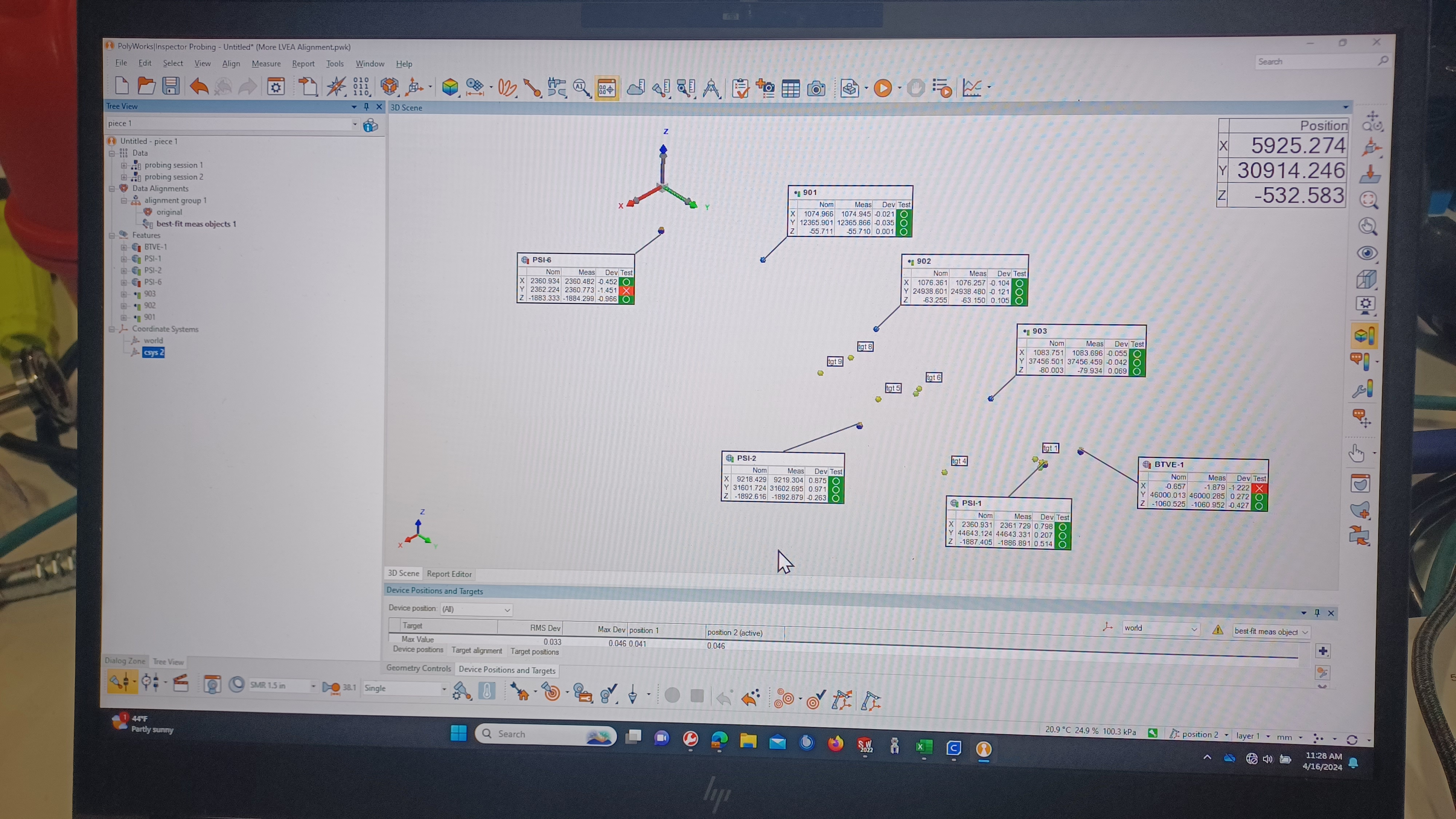
We also took another shot at converting from the LVEA local coordinate system to our site global coordinate system. We did this in the same was previously, setting up a new coordinate system and rotating the X and Y axes by our known rotations. We immediately saw that, again, it appeared to be over-rotating. I didn't get a picture, but using height mark 901 as an example. It has an LVEA local Z axis coordinate of -55.2 mm, which, when using the listed X and Y coordinates for this mark, translates to a site global Z axis coordinate of -55.7 mm.1 The new coordinate system kept putting the gloabl Z axis coordinate for 901 at -56.0 mm, 0.3mm below where it should be. We were a little puzzled by this, and were initially thinking that PolyWorks was rounding up to the displayed number of digits after the decimal point, and not using the axis tilts as we entered them (for example, Y axis tilt in degrees is 0.000716, which the PolyWorks display rounds up to 0.001). We set the display to 7 digits after the decimal and our entered angles were display properly, so this was not the cause. Turns out it was a sign issue. We had been told by PolyWorks support, back in 2022, that we needed to enter the opposite sign of our actual axis tilt due to the way PolyWorks references tilts w.r.t. the FARO. We checked the Properties of the new coordinate system and noticed the IJK unit vectors for the Z axis did not have the correct signs. In fact, it had both X and Y rotations listed as negative, when they should be opposite. Correcting the signs the displayed the correct global Z axis coordinates; shown in the final attachment. We still have the issue of the new coordinate system also rotating about the Z axis when it shouldn't. This is best seen by looking at the nominal X axis coordinate for BTVE-1. In the 3rd attachment, in LVEA local, BTVE-1 X is properly listed as 0.0. In the final attachment, in site global, the nominal X for BTVE-1 is now -0.657mm. In looking at the direction cosines for the LHO Corner Station as listed in T980044, there is a small rotation from global Z to local Z, which we did not implement. Will test and see if implementing this small rotation corrects this.
We like this alignment, it's the best we've seen to date. So, next steps are to start moving the FARO through the LVEA and measuring known points while setting up a volume of alignment monuments, in hopes that we can get enough monuments so we can set the FARO anywhere in the LVEA and be able to align it. This will continue on Tuesdays as our schedules allow, until we are done.
1) Keeping this here for posterity, as it was my thinking as we were on the floor, but this is incorrect. In writing this alog I realized that I got my direction cosine signs flipped when we were setting up the coordinate system transform in the PolyWorks software this morning. *facepalm* The proper global Z for 901 based on the X and Y axis coordinates listed in the referenced picture is -54.7 mm, not -55.7 mm. This also means that we then flipped the signs for both direction cosines when we "corrected" the incorrect signs we initially saw with the new coordinate system. I'm going to take a look tomorrow and see about correcting this, pretty sure we can do that "offline" without a FARO connected. Will post any update as a comment to this alog.